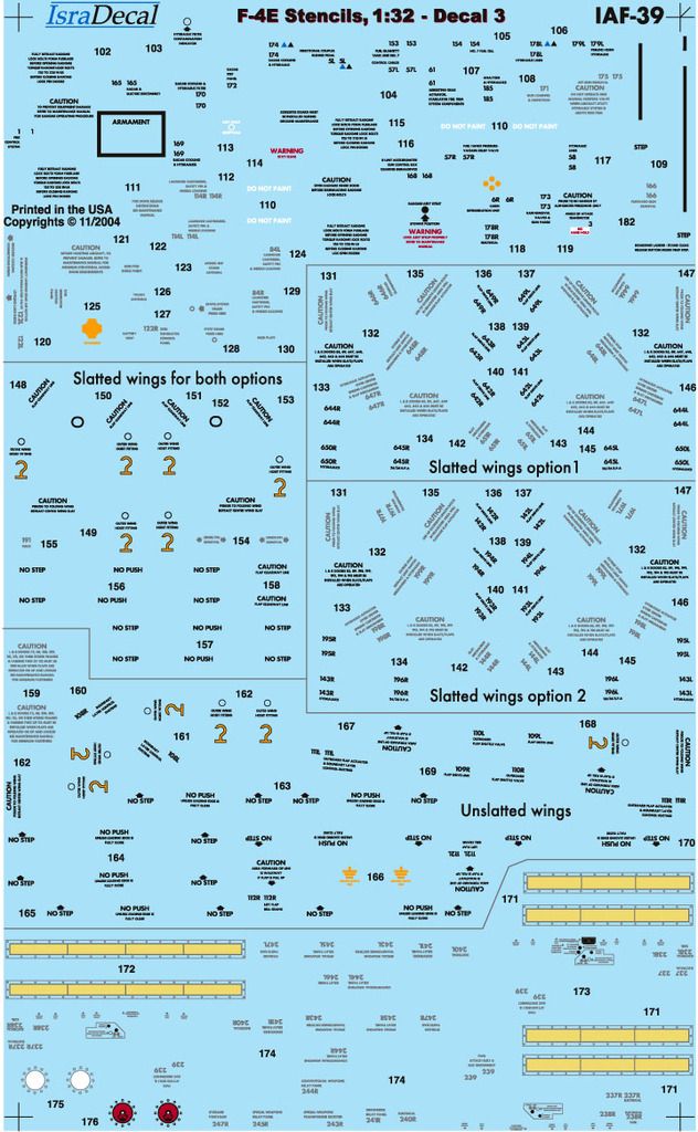
It has been a while since my last post in this build thread. That was due to varying reasons, lack of modeling MOJO being one of the main ones. Luckily for me that has returned so I can continue on this build again. Even during my MOJO slump I have not been sitting totally idle. I have been doing research for some scratch built items that I’m going to include. I have also been in contact with Isra Decal Studio’s to find out what the main differences where between stencil decal set IAF-40 (RF-4 set which I have got) and IAF-39 (the F-4 counterpart set that has been out of production and out of stock for some time now). The owner of Isra Decal Studio’s was very helpful and was able to send me a spare sheet of the needed stencils mainly for the nose, slat wings and TISEO pod. One of the things that was supposed to be included in both sets was the stencil data for the outboard / external wing tank pylons. Here is a photo of the spare sheet that I have received free of charge.
One of the things that were still missing from the stencil data are the decals for the outboard wing pylons and the ECM Pod. As the aircraft I’m portraying almost always flew with the ALQ-119 (long) ECM when it flew with the 32nd TFS. I had a look on scalemates and there I found out that previous releases of the kit I’m using had all the decals included I’m currently in contact with Abtailung X at Revell to see if I can still obtain them.
When I left you last I had just painted the Nose Landing Gear Bay. That was done because the forward fuselage had to be assembled before the test fitting of the GT Resin Cockpit could commence. The forward fuselage came together easy enough, there were some issues though, large panel gaps, missing and incorrect panel line details and some uneven kit part joints. After I installed the Corrected Nose also from GT Resin I had already found that not all the kit panel lines where meeting up as I would have liked, where missing or just incorrect after checking the reference material that I have gathered for this build. To address this issue I have compiled a re-scribing list of all the panel lines that will have to be “fixed”.
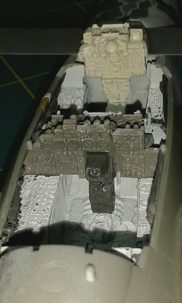
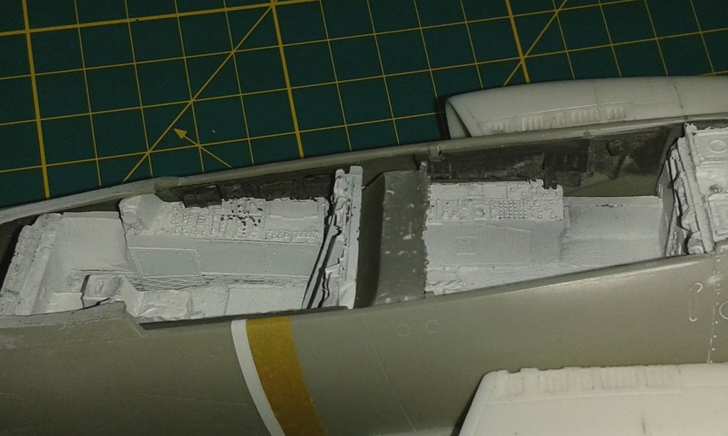
The cockpit itself was an easy slide in replacement with lots of fine detail that was void in the kit office. Even so it is still getting the Eduard Interior PE treatment to enhance the detail even further. Here are some photo’s of the cockpit during the test fit preassembly stage.
After the forward fuselage mod’s where done and test fitted it was time to start on the rear fuselage modifications. These included Seamless intakes, corrected vertical stabilizer Fin Cap and Exhaust conversion. These where all included in the GT Resin Shipment that I had received prior to the build.
The seamless intakes required some major plastic surgery of the kit parts to make room for these as the design people at Revell had a day off when it came to doing the internals for the kit intakes. The kit intakes where therefore null and void when it came to this build. The effort put in will definitely pay off in upgrading this kit. The cuts were made in both the forward and Aft. fuselage sections, wing bottom and the forward fuselage bottom. Now that access was provided the intakes itself could be test fitted.
As you can see in the photo’s above something went “wrong” during this stage. The photo’s in the instructions where grainy small black and white ones so picking out the fine detail was very hard to put it mildly. As the aftermarket manufacturer GT Resin Is one of the contributors to another forum it was time to take a look over there to see if I could find any info and photo’s there, man o man that was easier said than done. So after being unable to find the info I needed there I contacted the seller directly. He came back with an initial reply within the hour, not bad considering I’m in Western Europe and he is located in sunny Florida in the USA. Taking the time difference into account I can only imagine that he must have been working late as it was around 1am in the morning. Got to love the cottage industry manufacturers that are still out there in the world of aftermarket.
After a short back and forth over the email, Garry (owner of GT Resin) provided a better walk thru of the fitting instructions and also provided some very high resolution color photos that showed all the aftermarket he makes fitted to the latest 1:32 Revell Release Phantom the F-4G. As I had previously built this model out of the box in my younger days I never noticed that the kit intakes where t wide. But this totally explained why I was having difficulties in fitting the correct size and shape intakes. The photos that I had received also clearly showed that a quick sanding and filling job could remedy the mismatch. However as I was also going to fit resin combat strike camera’s to just under the intakes the easy fix was not going to cut it, as this would only highlight the problem area even further. After checking my reference material to find the correct location of the combat strike camera’s I noticed that I would have to perform some real world to modeling world magic to get them to look right. The curvature in the access panel was also very nicely portrayed in its kit counterpart and was even a glue in item. No problem one would assume, but the resin camera’s available are made for the Tamiya F-4’s and I’m building the Revell F-4…. Needless to say now the same mismatched panel on the intake side now also needed work in the back to get the flat resin camera to fit the curved panel. As the transition has to be smooth and straight I decided that a removal of the outer curve with a razorsaw, reworking the part and fitting it in the corrected shape would leave me with a nicer fix.
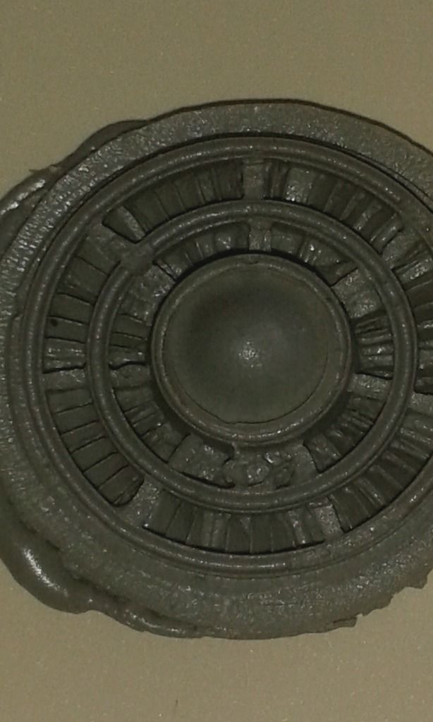
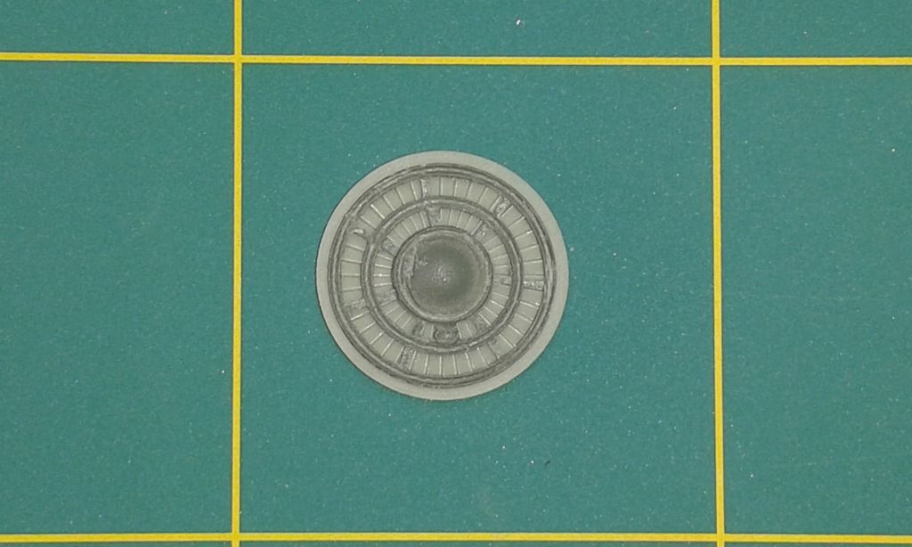
The seamless intake set also included General Electric J-79-17 fan faces. The intricately cast parts had some casting issues and transportation damage on them. Some broken fan blades and hard to clean excess resin overflow.
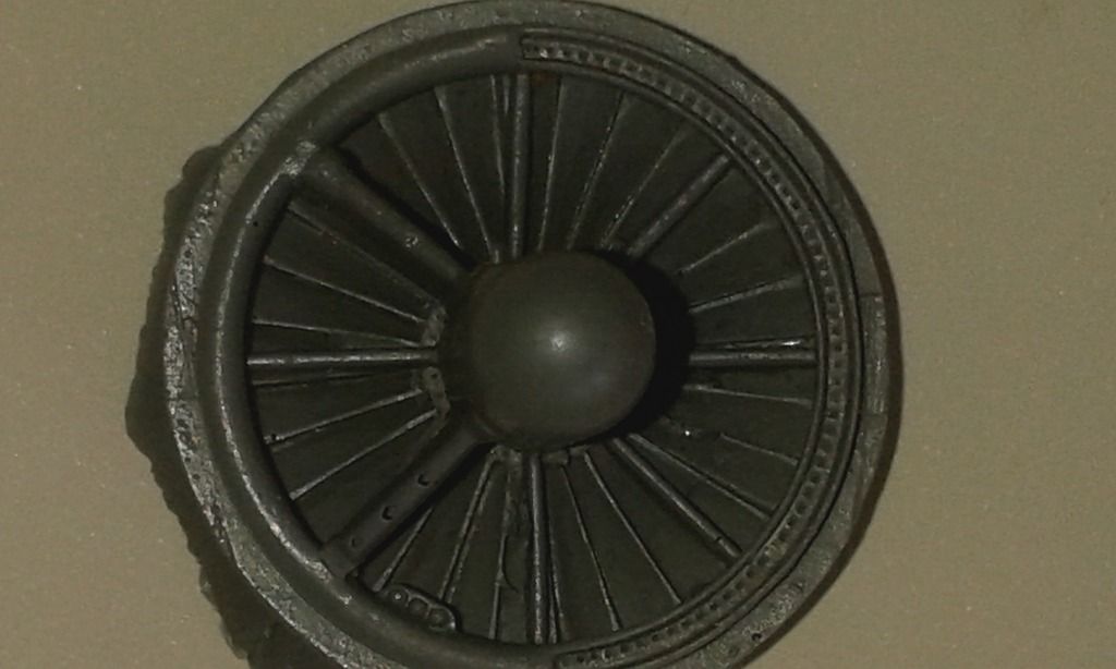
As the aircraft I’m portraying in this build was delivered new to the squadron from the factory a fix would be in order. The kit does contain plastic fan faces and engine intakes which would come in handy for the fix I came up with. As the resin parts also contained varying sized casing blocks that would interfere with the kit reinforcing bracket with the fan blades on them sanding them down to beyond the norm would leave me with just the engine intake.
Here’s a photo to show the intermediate that I now had.
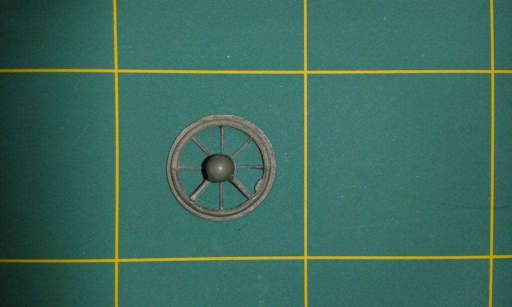
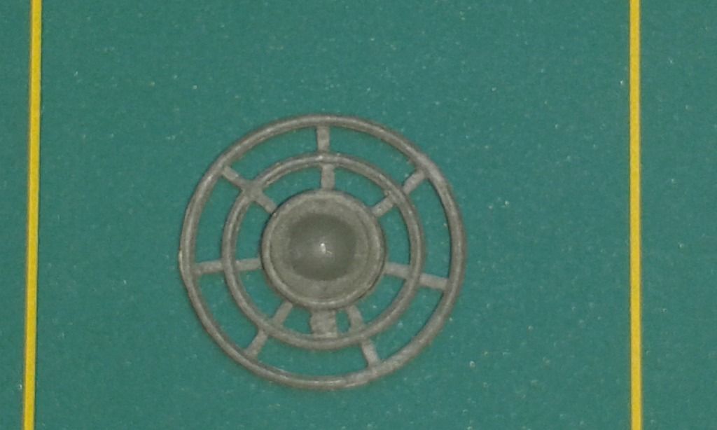
Time for a test fit. This revealed that the injection molded fan-blades from the kit would also need some tinkering to get an accurate end result. Some 0,15mm sheet styrene and a 10mm hole punch came in handy. Here’s a photo of the created plastic discs fitted to the bulkhead with Tamiya Extra Thin.
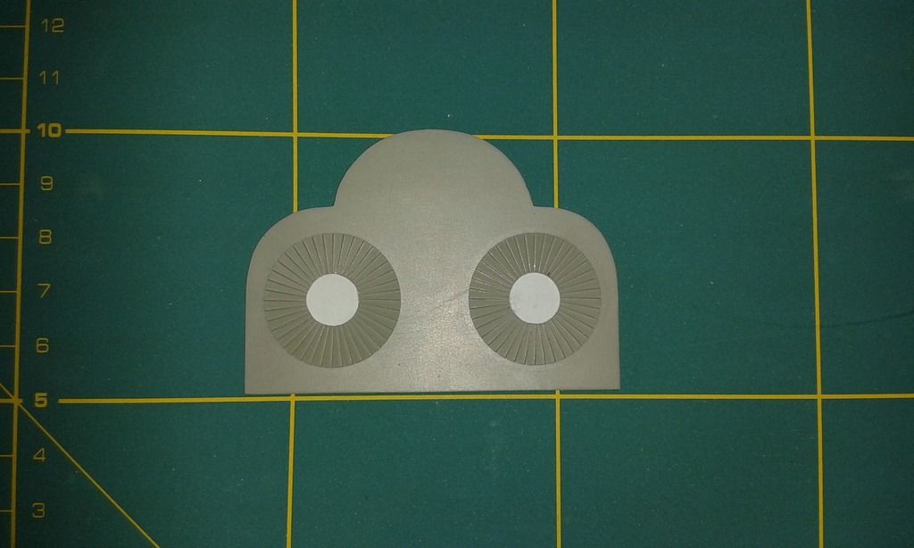
As the kit bulkhead will be sacrificed in this repair an new one was made up out of sheet ABS of the same thickness as the kit part. Some carving of the fine detail is still to do to get the fan blades to meet up accurately. I will do my best to get something looking like this.
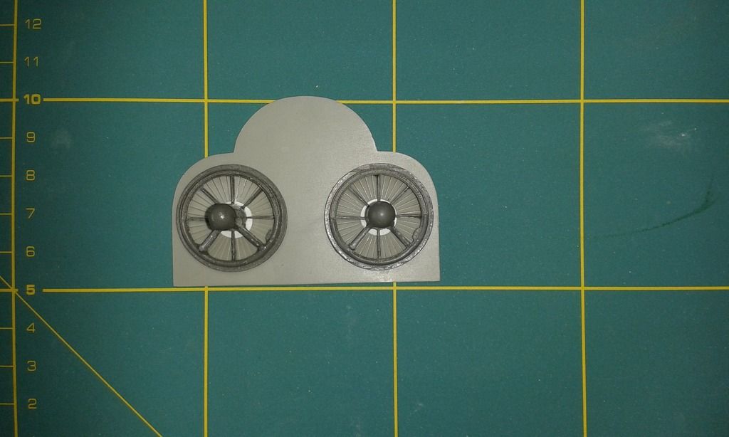
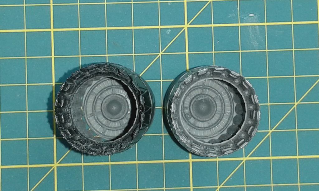
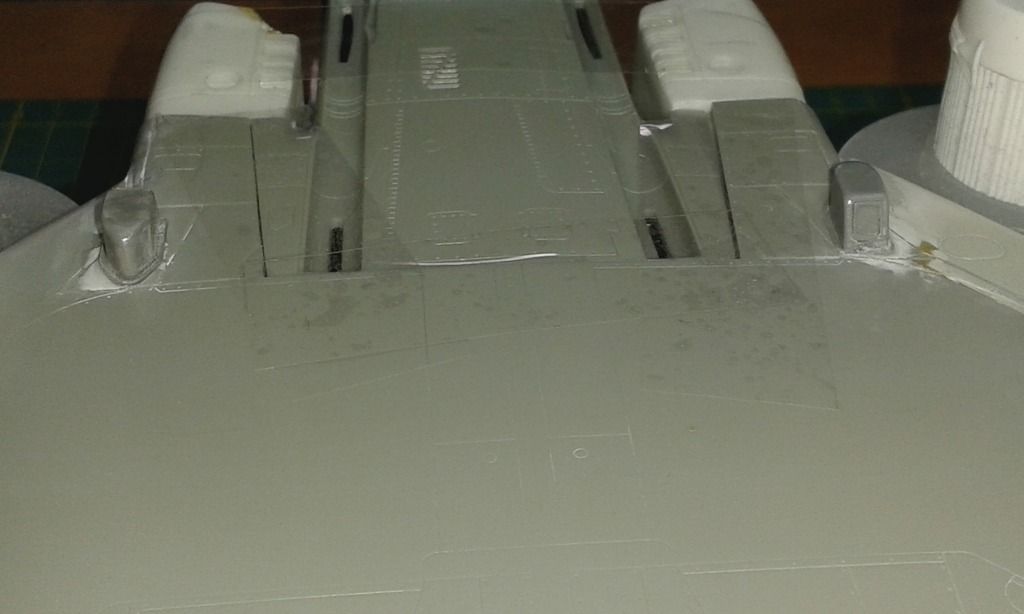
After the intakes it was time to start on the preassembly of the other end of the GE J-79-17 Engine. The GT Resin Kit for the exhausts is wonderfully cast and contains the turkey feather nozzle, a jet tailpipe and a turbine face with afterburner rings. The only small drawback was that the turbine face had some of the same problems as the intake, in that it had some overflow in hard to clean places and some of the blades themselves had casting defects. The kit parts for the exhaust came to the rescue ones again. The cones where cut down to leave me just a thin disk with the turbine blade detail injection molded in. The resin parts where sanded down in the same way as the intakes. I used sheet sandpaper in varying grades on a glass plate to get a flat end result. Here are some photo’s to show the steps and end result.
The resin jet tailpipe was much longer than the kit part. The kit aft. fuselages halves needed a relief cut so that it would not interfere with a correct fit. The removed parts where set aside as the where nice flat and thick styrene, they would come in handy later on in this build. The resin nozzle and tailpipe both had reasonably sized casting blocks and required only little works to get them off. A nice touch ware the scribed in cut line to aid in removal and something not found in some aftermarket. The parts also fit together snugly so only a small amount of medium or thin CA glue will be needed during final assembly. This is a point that I’m reasonably impressed with as GT Resin is only a Mom & Pap after market manufacturer.
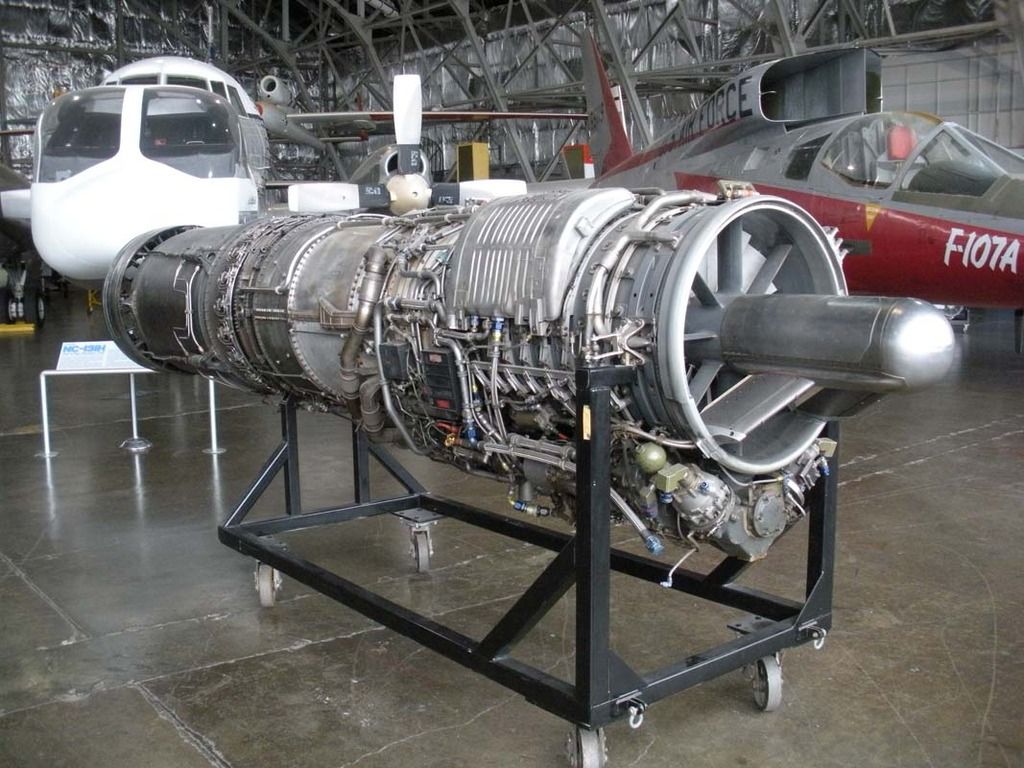
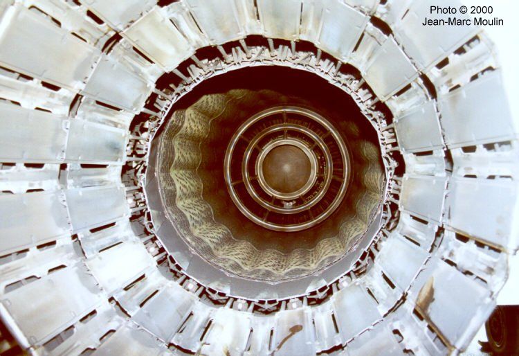
Here’s a photo of the real thing that might come in handy in other builds
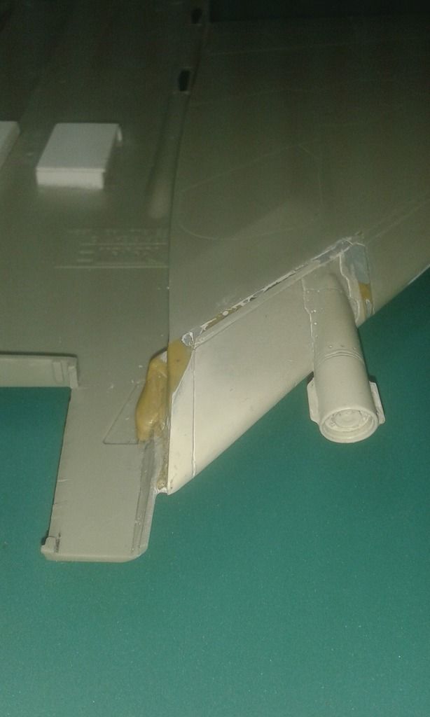
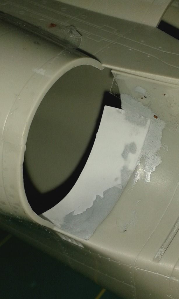
A test fit of the pre-assembly to the aft. fuselage pointed out one of the faults with the kit. The exhaust heat shield aft. of the jet tailpipe fell short. This left light coming thru where the nozzle meets the fuselage. Some 0,1mm sheet styrene was used to make a almost perfect circular repair. Now it represents a more accurate depiction of the real aircraft. This point was also evident when I built a previous version of this kit in my younger days. I also did a similar repair back then.
Here’s a detail shot of the repair. White is the sheet styrene, Gray is standard Tamiya filler to get a supper smooth transition. The later is not absolutely necessary as the will be hidden behind the nozzle but hey I’m a stickler for detail.
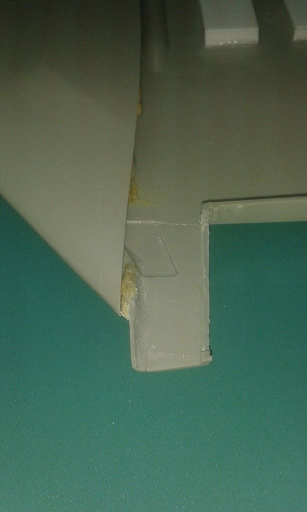
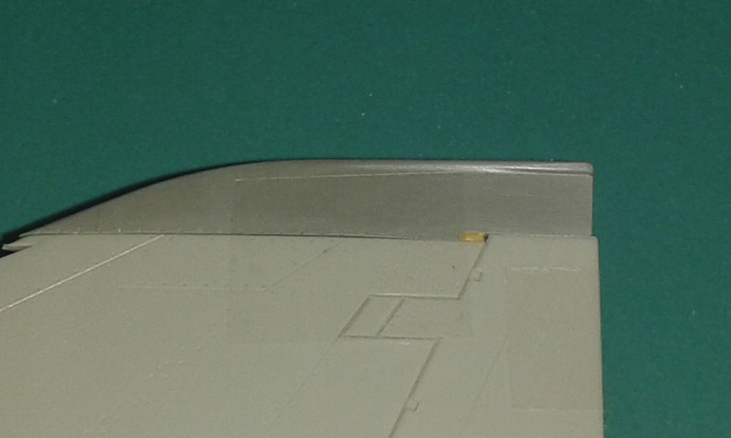
The kit Fin Cap included in the kit for the F-4F is one of the other known faults with the kit. It is shaped incorrectly for any F-4 Including the F model for which it is intended. The Conversion Set from GT Resin includes a correct Fin Cap to address this issue. It also has a small issue with it as it. The part of the cap where it meets the rudder is about 1,25mm to short. A bit of Tamiya Epoxy Putty made light work of that little snag.
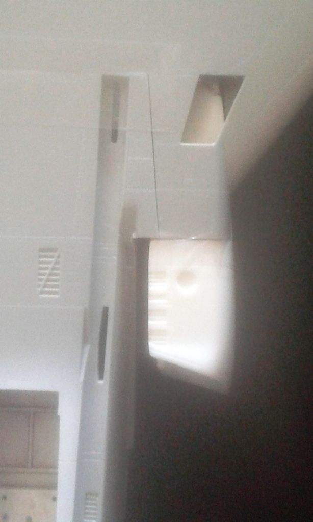
Now that the aft. fuselage was also done it was time to start converting the wings. The modifications being done include: Resin Slat Wing outer wings, TISEO in the leading edge of the left wing, Placement of resin combat strike cameras and opened up auxiliary air doors as those where almost always open on the ground including scratch built interior.
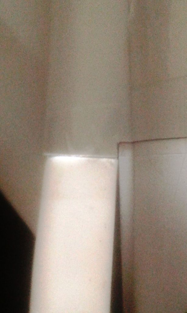
The outer wing modification was undertaken first as this mod required the removal of the end plate of the inner wing. As this would be almost impossible after the inner wing would be glued this was first on the list. The kit preparation work was well described in the instruction that came with the resin parts from GT Resin. The resin outer wings are full of detail and are a well worth investment over the very basic kit alternatives. There only a couple of small issues, the surface texture of the resin part still includes the milling marks of the master mold. The other one is the inclusion of an access panel on the underside of the right outer wing which should only be on the left side. The last one is that the scribed detail on the underside on the wingfold hinge is a bit soft and could de with a re-scribe. These are all minor issues in my opinion as the modification itself will require sanding, filling and re-scribing to get the optimal end result.
After the outer wings where on it was time to tackle the TISEO. The kit panel lines where almost correct but left me with a cut out that way too big for a straight in replacement. As the wing root also needed tweaking to fit the resin intake this was undertaken at the same time this had a positive effect on the fitting of the resin TISEO pod that was a one piece casting with the leading edge section. Because there was no positive guide to the placing of the replacement leading edge section after removal of the wing root section the access panel that would hold the combat strike camera was glued in place. The resin leading edge section had a notch to accommodate that panel so the inner positive stop was ones again there. The leading edge section was glued in place with thick CA Glue that would also act a preliminary filler for the mismatched gaps. The inner and outer gaps that where left where then filled with Tamiya Epoxy Putty. As the wings are of a hollow monococque construction on this kit without any reinforcement the inner wing joint would be not as strong as one would like where it will meets the aft. fuselage. Reinforcement blocks of Tamiya Epoxy Putty where made up to solve this issue. This also fixed the wing shape issue that is on the kit discrepancy list.
The cut outs for the auxiliary air door where made using nano PE saws from RB Productions. I used scribing tape to outline the panel that had to be cut to get nice clean cuts. 0,25mm Sheet styrene was used to create a box that would hold the interior detail which will all be scratch built just prior to final assembly to minimize the risk of it getting damaged.
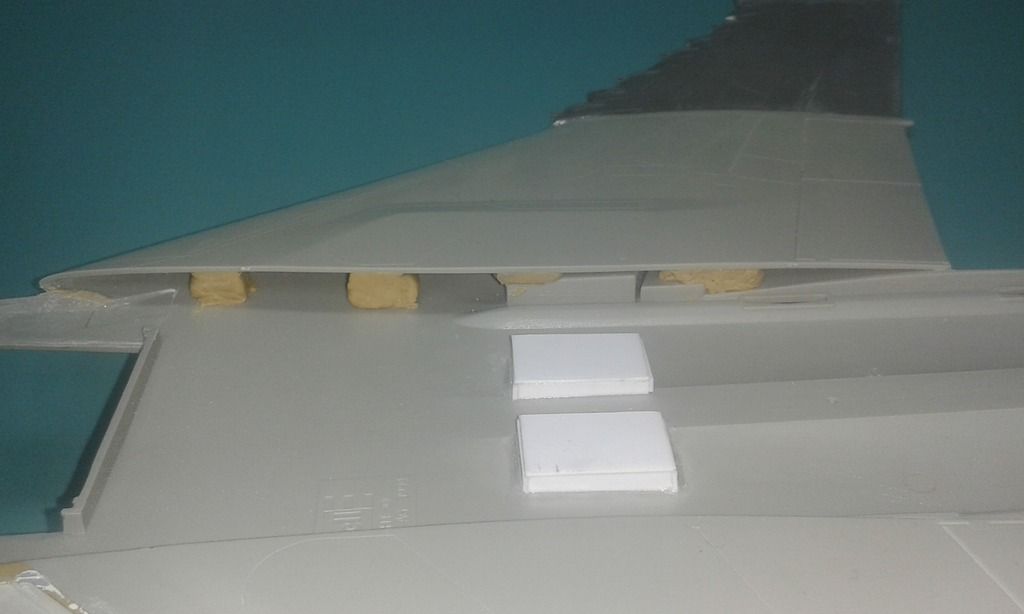
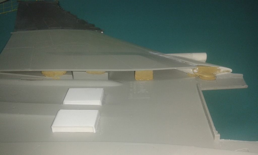
The combat cameras where the easiest of the modifications as they where a glue on and fill addition to the wing. The access panel and the wing root panel required minor filling to get a smooth transition from the bottom wing to the resin intakes.
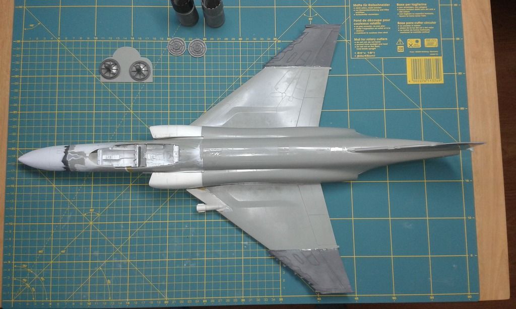
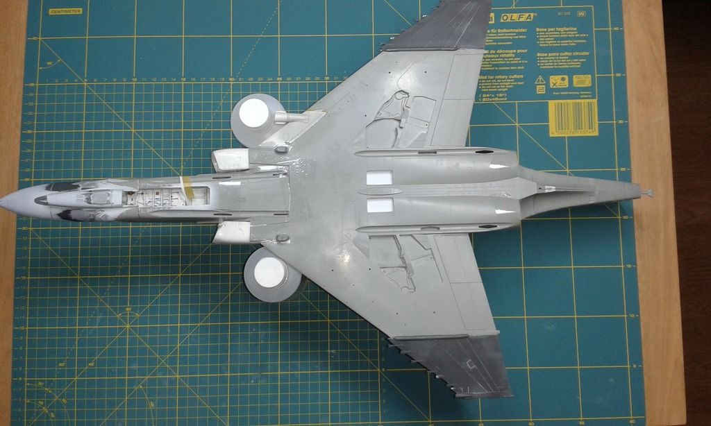
With the wing now also pre-assembled it was time to start on the final assembly. But before I started that I was a nice opportunity to test fit the semi completed build. I used clear cellophane tape as this would leave me with a good indication of any gaps that would occurre during final assembly. This also was a nice photo opp. To show of all the modifications and alterations that have been made. The light gray is the kit plastic. All other colors are resin, filler and sheet styrene.
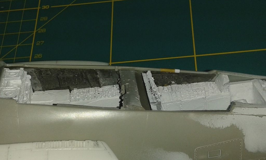
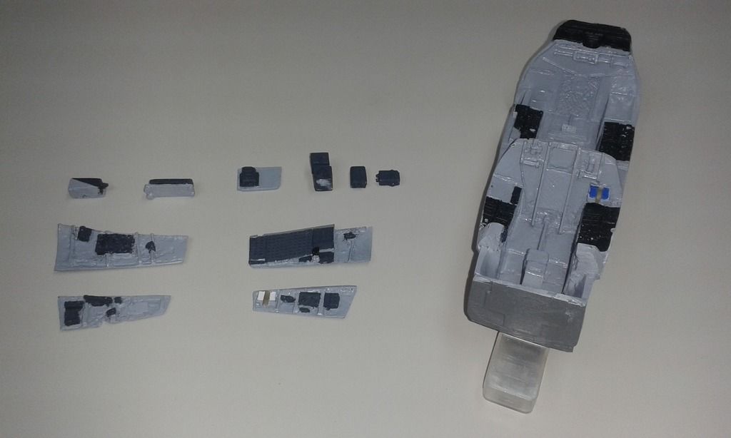
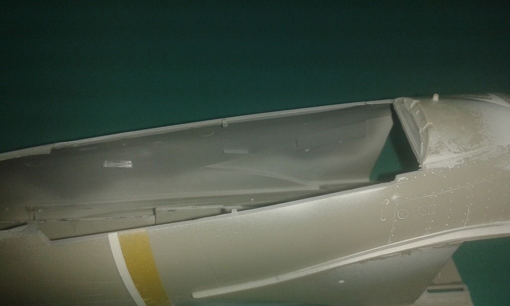
Now that the major modifications where done it was time to start with the final assemble. I opted to start with the forward fuselage that contains the cockpit that has been whispering build me, build me for some time. The resin cockpit tub had already been primed in white after the PE details had been added to it. The resin side walls and ancillaries where taken off the casting blocks and cleaned up prior to test fitting them. After I was satisfied all the part would fit and look alright it was time to spray them in Ultimate White primer ones that had time to cure the base color went down. I used Mr. Hobby Aqueous H306 (FS36270) as this was a close match to the color on the pre-painted PE from the Eduard set. At this point a two small gaps became clear. One was on the right inner wall of the aft. cockpit, where there was a step visible from the intake spike in the outside of the fuselage. The other was a gap where the aft. cockpit deck meets the aft canopy hoop. The flat styrene pieces from the exhaust relief cuts where the correct thickness to solve both issues. Those were trimmed to fit their new home on the model and glued in place with regular Revell professional modeling glue. On the intake side of things a small step was still visible and that was filled using Tamiya putty. The inside of the forward fuselage was then primed in Ultimate White primer followed by the base color. After that it was time to start with the detail painting of the cockpit. Here are some progress photo’s of that as well.
That is all for this installment, as always happy modeling and keep sticking styrene.
Paul J