Re: McLaren M19A, Denny Hulme, 1972 US GP Watkins Glen.MFH, 1/20.

Cars, trucks and bikes
Post Reply
pg265
Sergeant First Class
Posts: 302
Joined: Sat Aug 24, 2013 10:09 pm
France

Re: McLaren M19A, Denny Hulme, 1972 US GP Watkins Glen.MFH, 1/20.

Post by pg265 »

Good evening,

In need of resin and metal, lover of the car, brand and its creator, it did not have to tickle me too long to throw my heart on this superb kit!

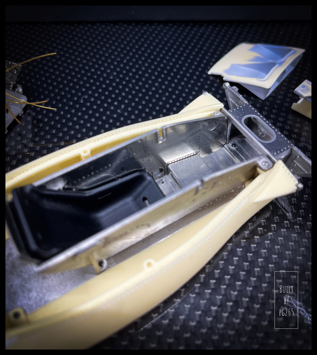
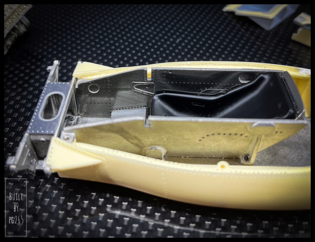
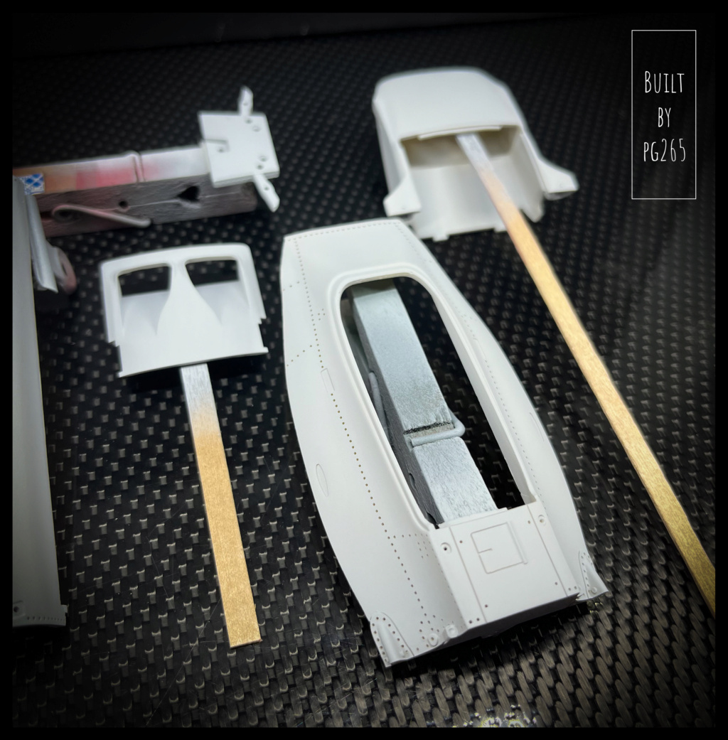
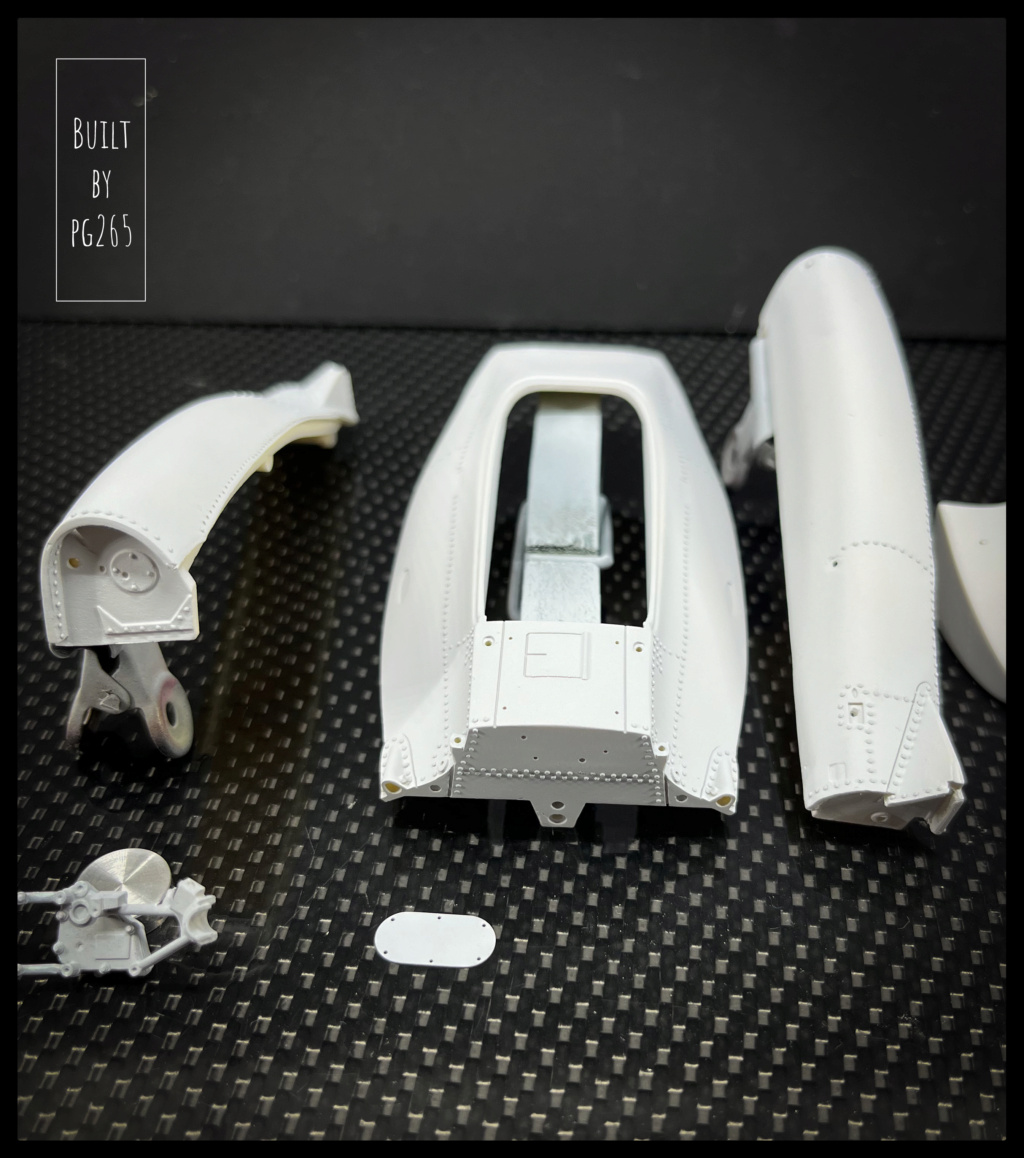
The White Metal parts of the cockpit are prepared and then polished.

Image

Image

Image


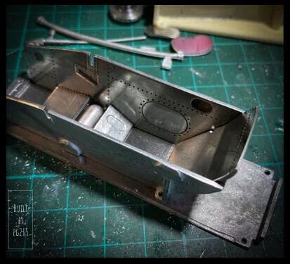
These elements will subsequently be partially riveted.

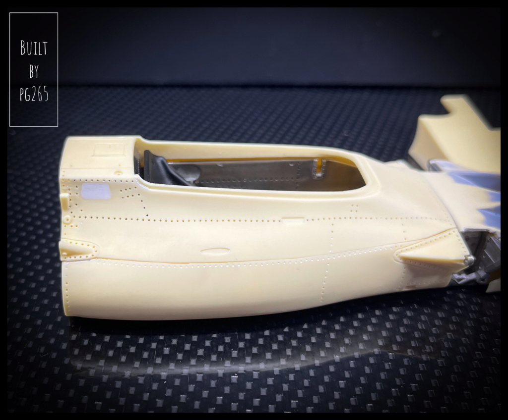
Same thing for the resin parts of the hull.

Image

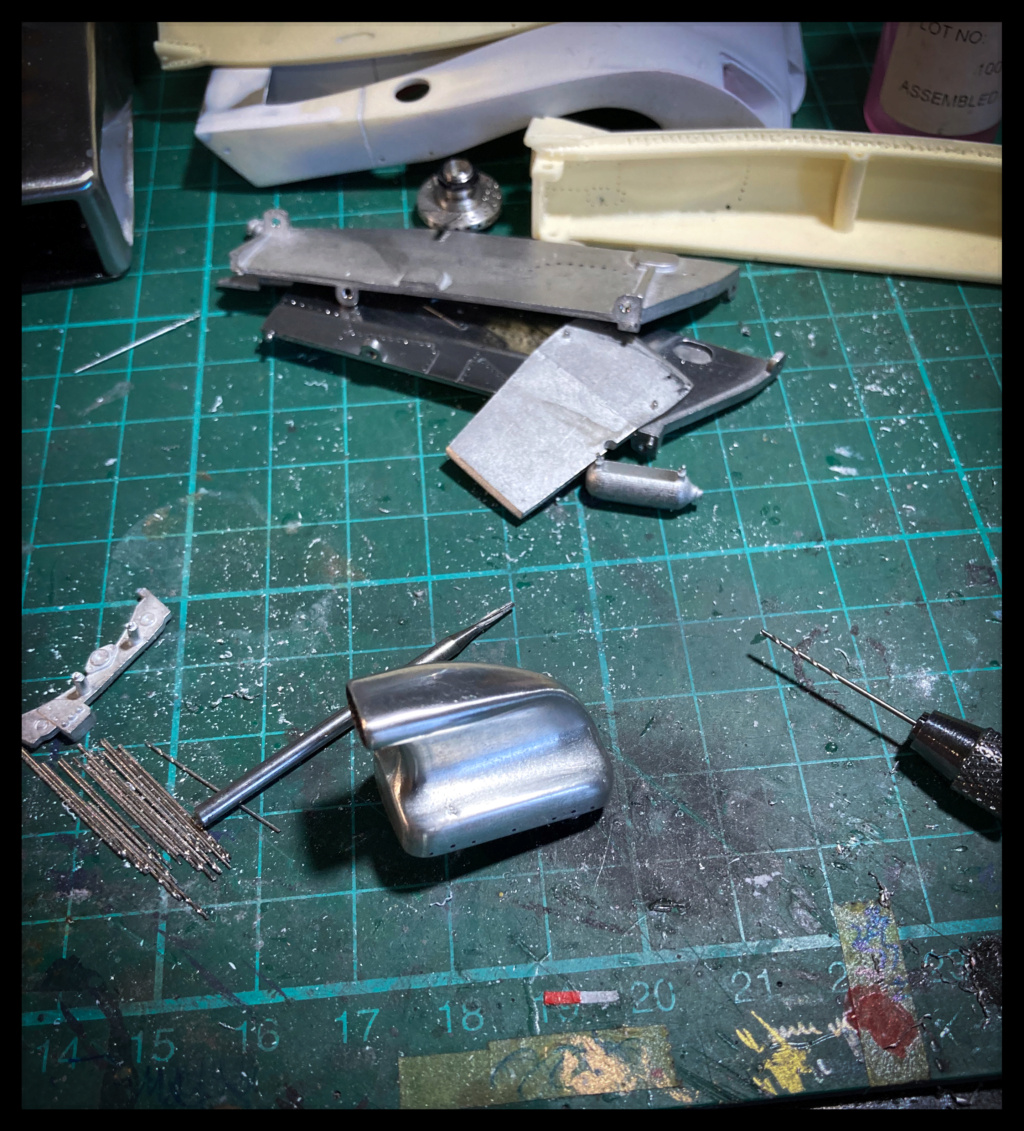
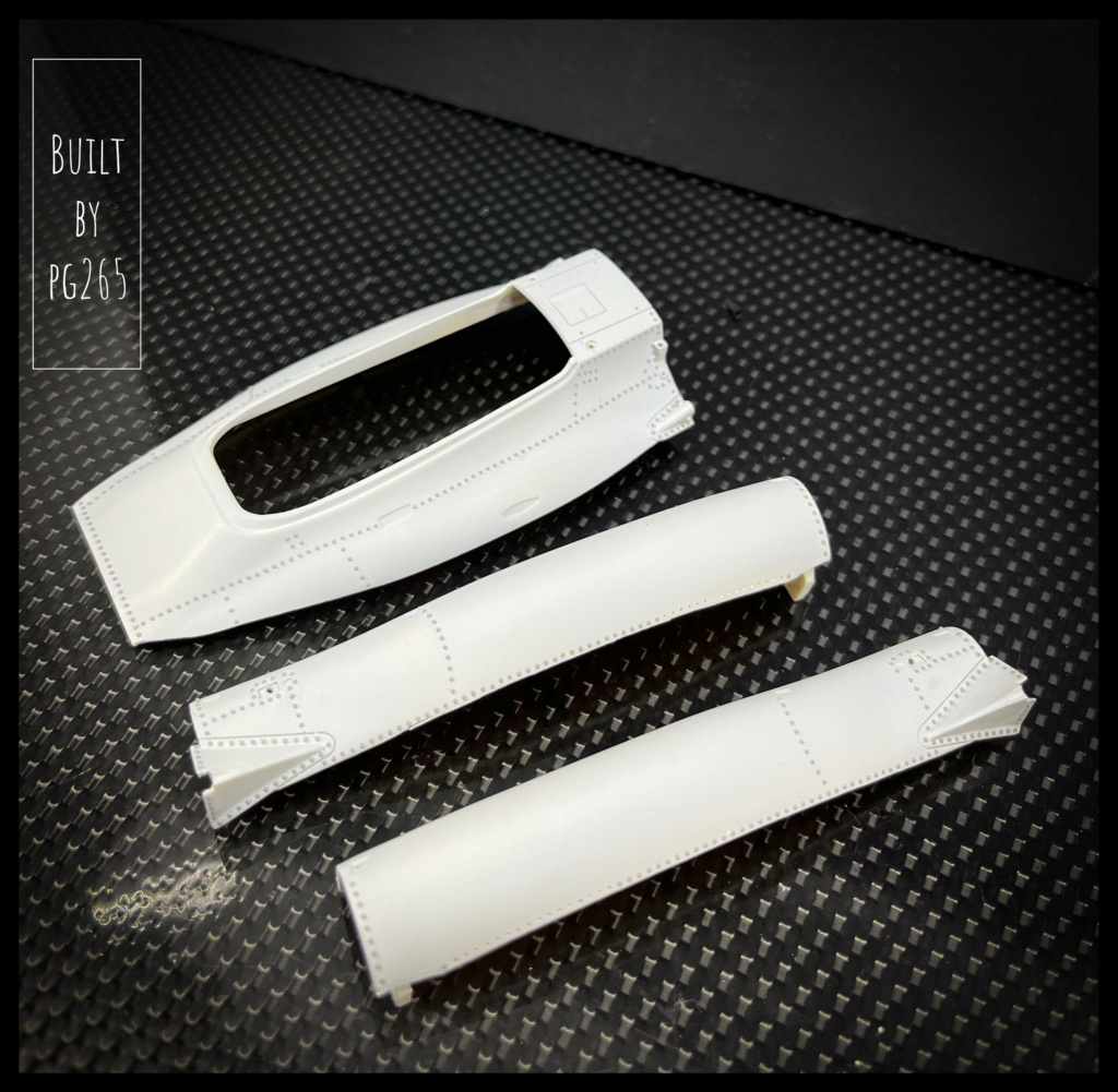
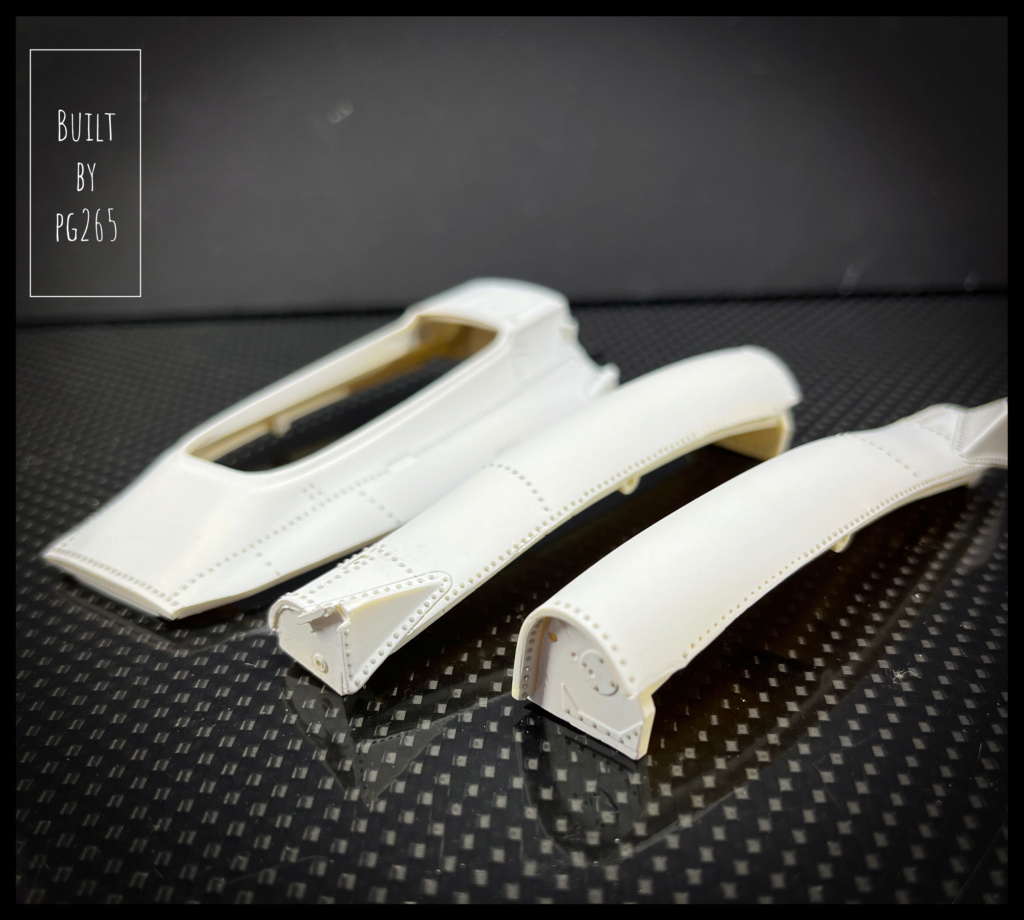
The advantage of the M19 at Watkins Glen lies in the different configurations for testing and racing: the kit makes it possible to represent this particularity.
The test nose:

Image

Image

Image

The one selected for the race:

Image

Image

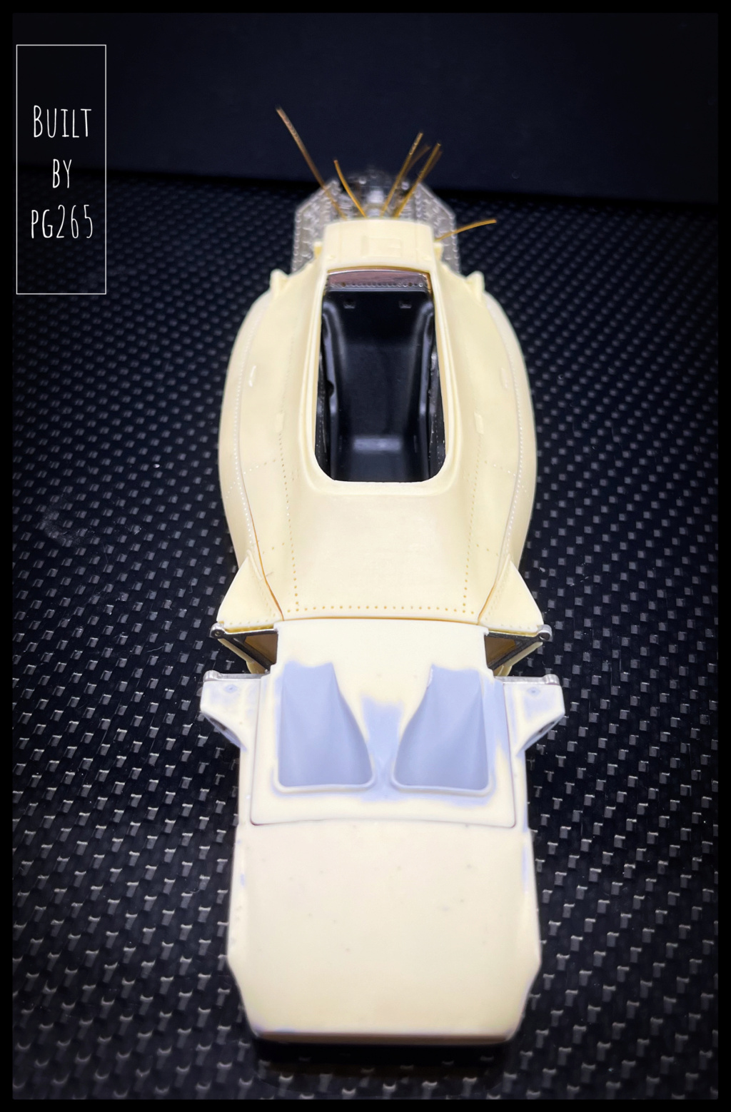
I prefer the race version, but the muzzle of the tests will also be mounted and presented next to it.

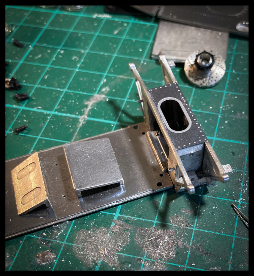
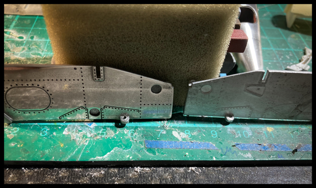
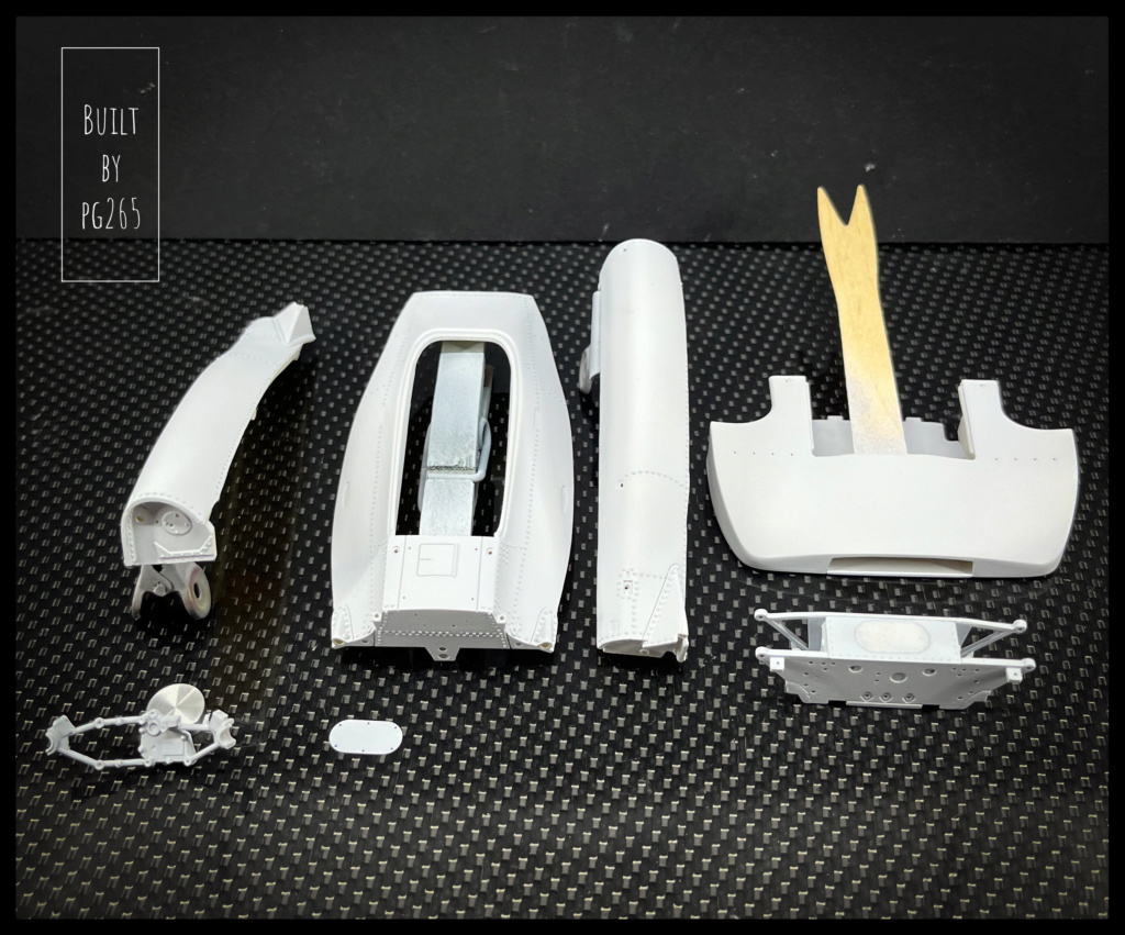
A few fit checks confirm the positioning of the parts.

Image

Image

Image

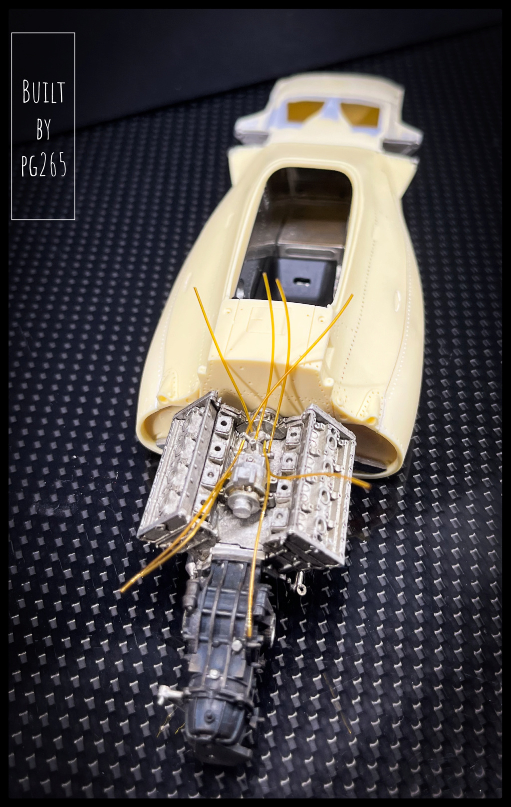
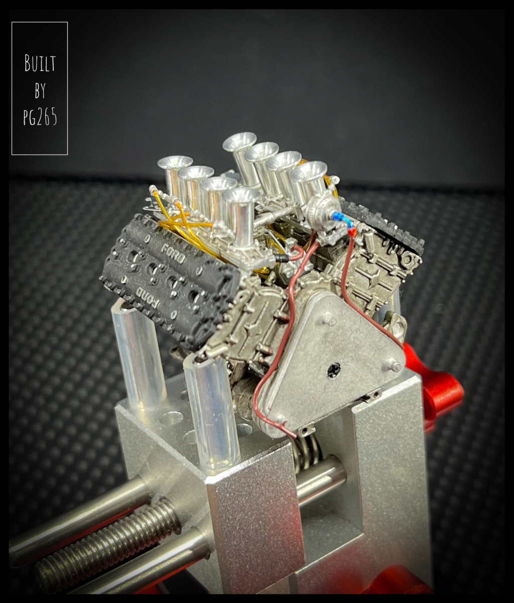
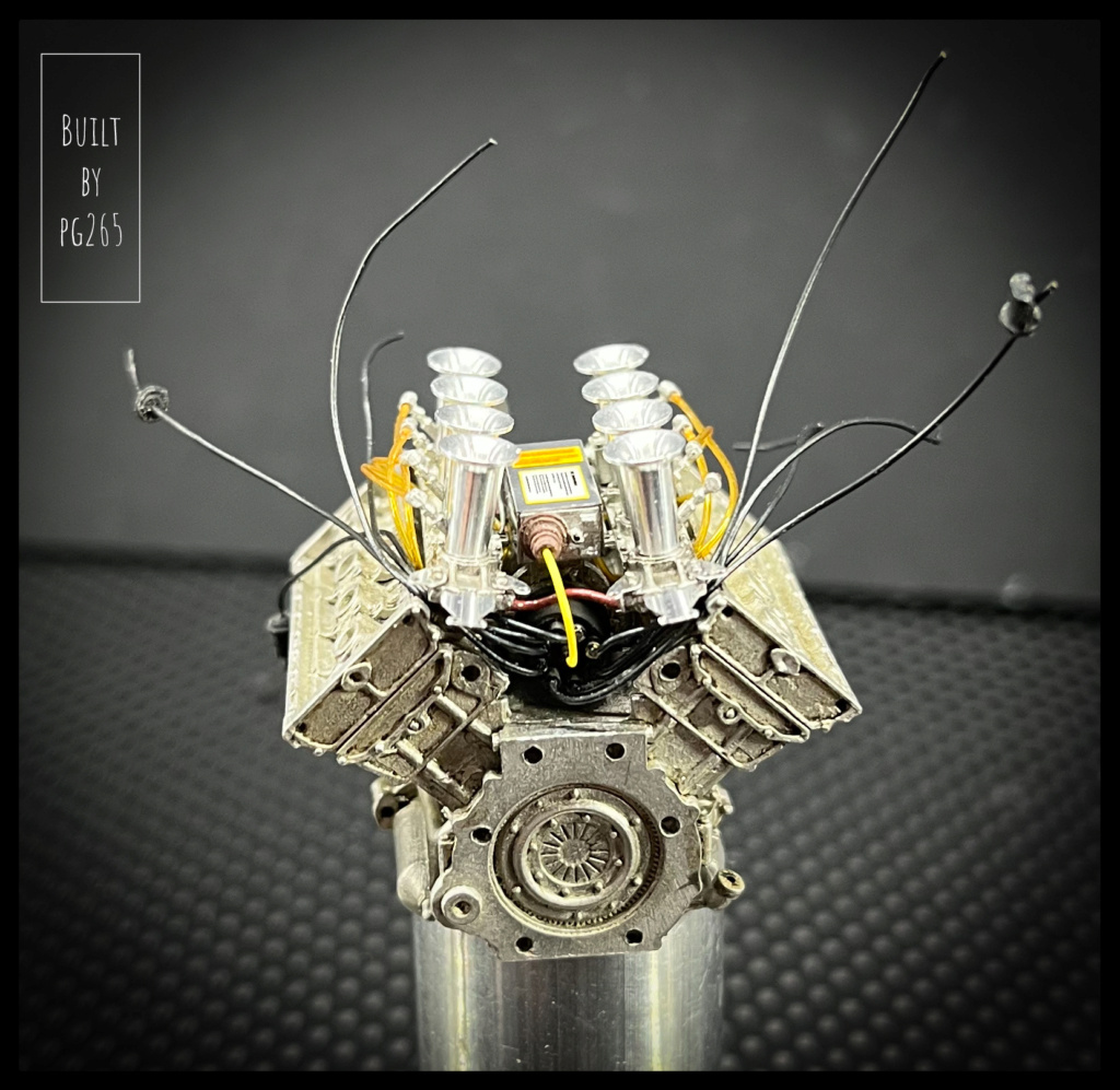
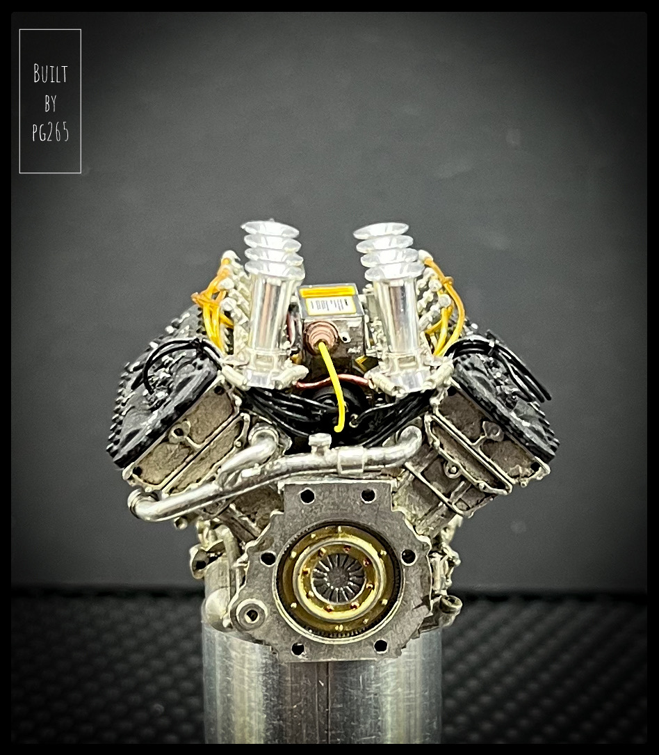
The engine, the famous and magical Cosworth DFV, fits wonderfully well.
It is extremely well detailed: the best restitution to scale... at least!
It is the same as the one on the M7A box, even the camshafts can be installed.

Image

Image

Image


Image

Image

Image

Image

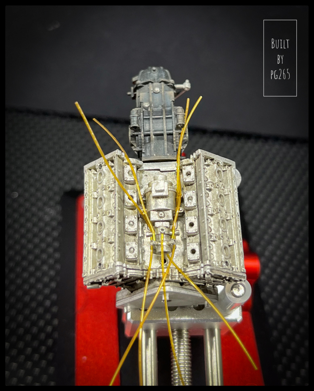
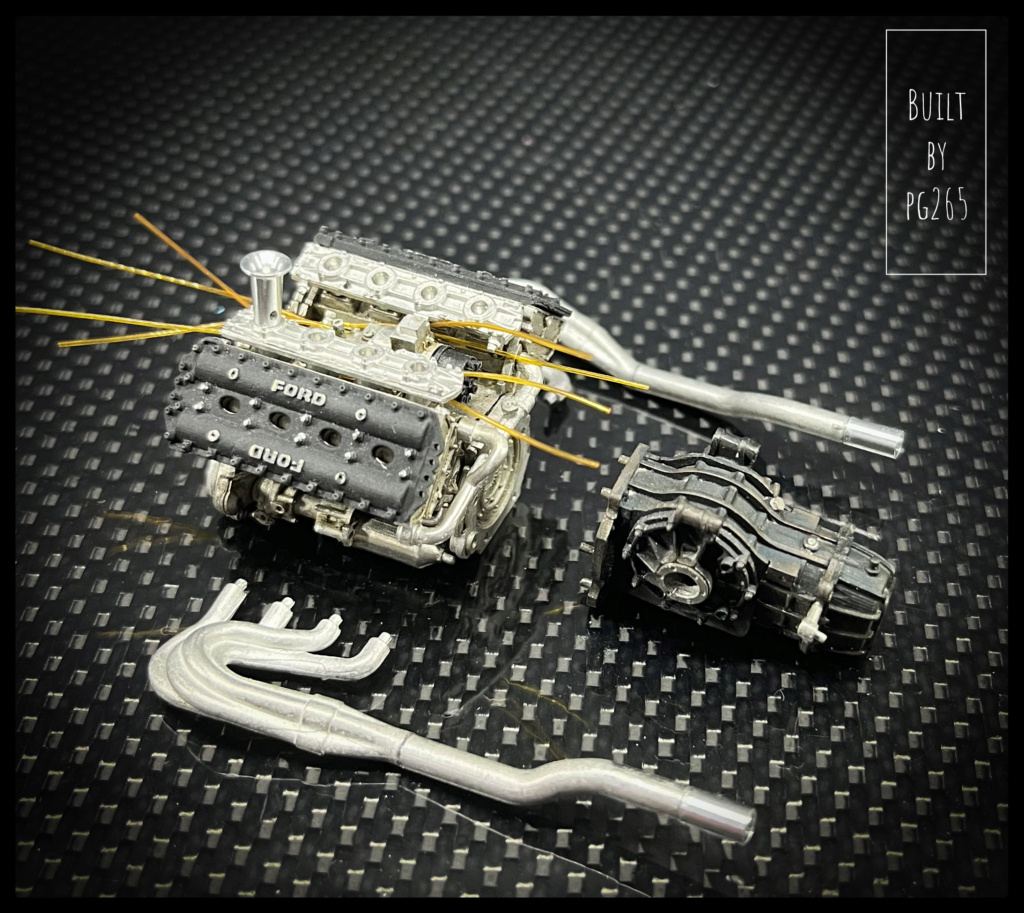
The cylinder head covers are painted in semi-matt/matte black, the other parts painted in various aluminium tones or just enhanced with oils.
The box is assembled and then «colored» by masking certain areas.
The hollows are again treated with oils, just like the reliefs with light dry brushing.

The sub-assembly is checked on the hull.

Image

Image

Image

The circuit breaker location on the side of the hull must be sealed for this version.

Image

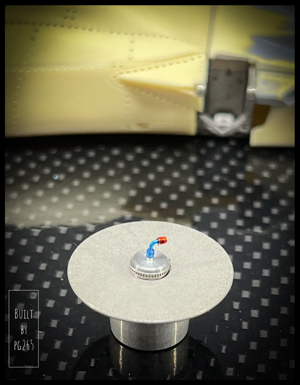
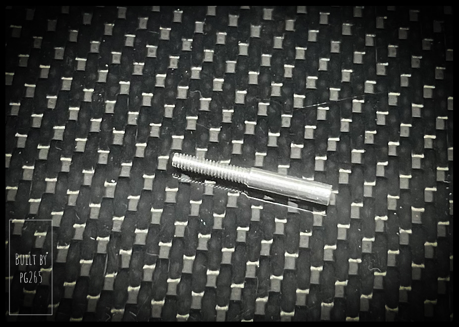
Not being completely convinced by the engine’s gas filter, I turned another one, equipped with a serflex and an A/ N connection.

Image

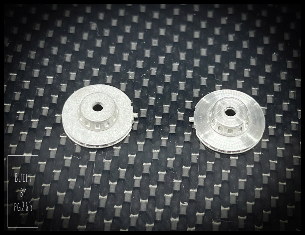
I am also leaning on the discs, scratched thanks to a small tool there again made on the lathe then threaded; I will make a photo.

Image

The parts of the oil tank are welded.
It will be painted very soon.

Image

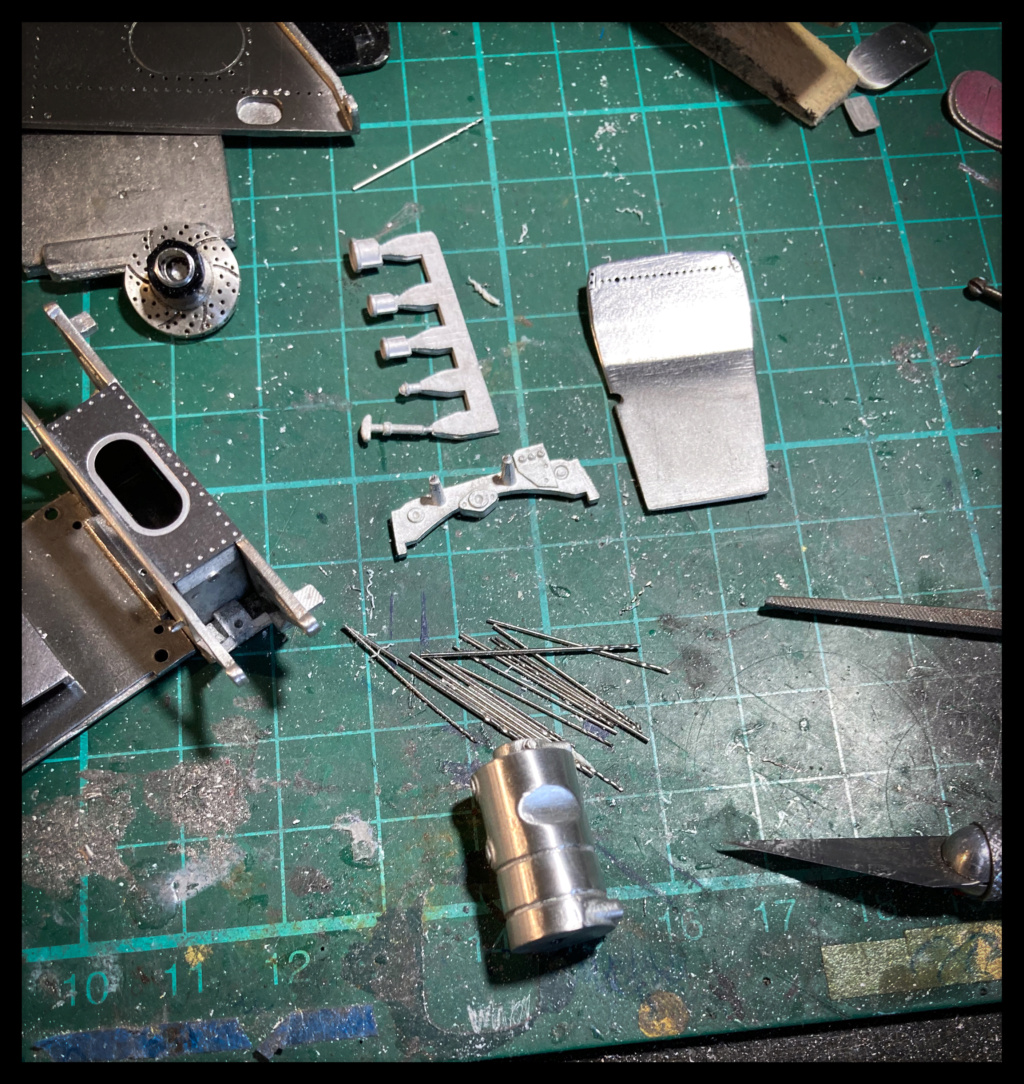
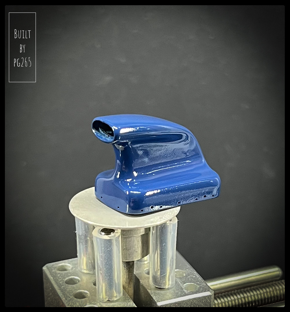
Same thing for the intake duct.

Image


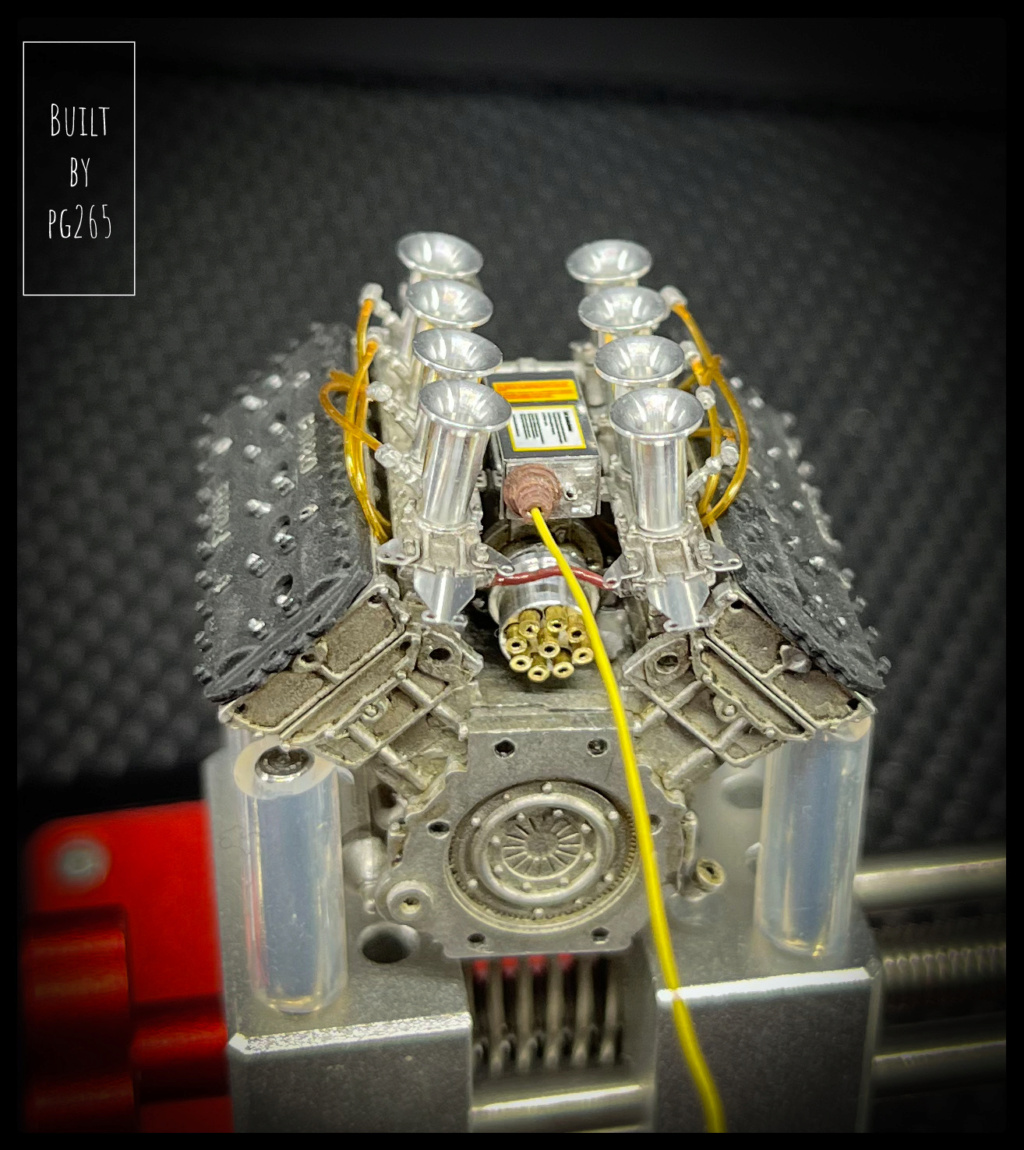
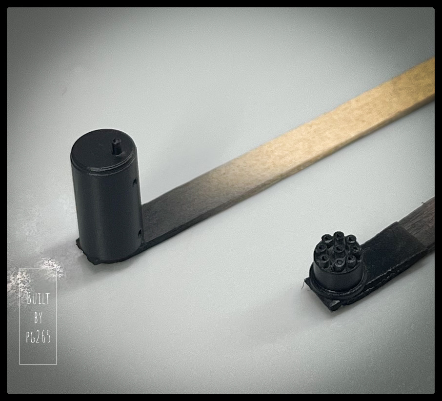
I met some problems with the Delco who ended up getting me really upset...
So I decided to make another one after taking the odds.

The main piece is turned in an aluminum rivet of 6.35, pierced in the center on both sides.
It is then drilled every 45°.

Image


Image

Image

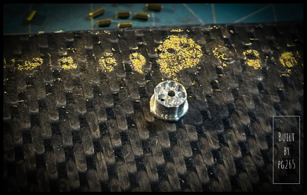
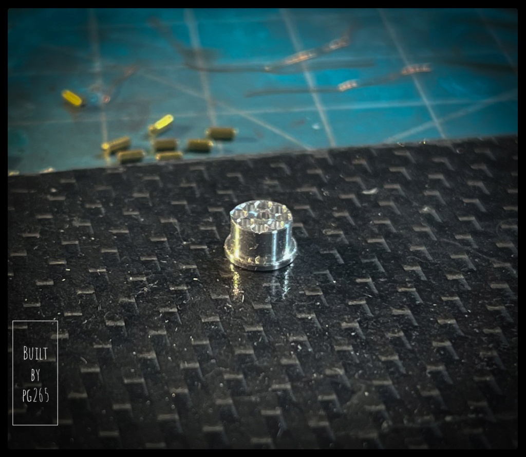
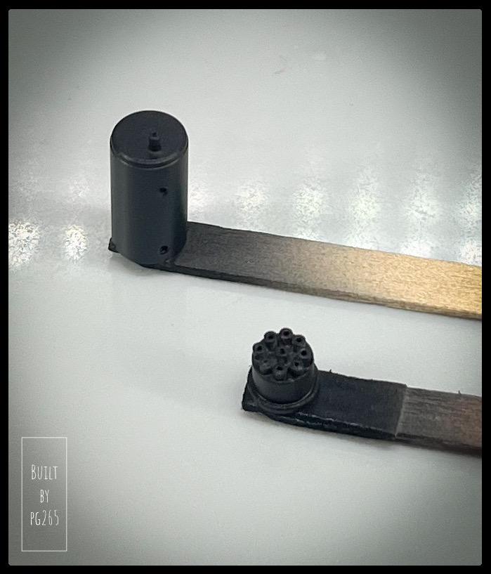
9 small «cannons» in 1mm brass tube are cut and then installed on Delco head.

Image


The « QFE (😇🛩️🥶) is reset » to the abrasive disc.

Image

Image

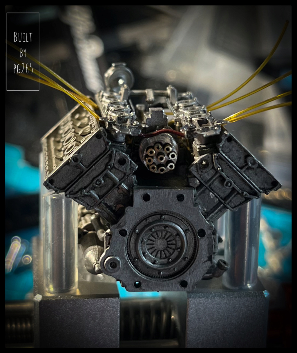
It’s not perfect, but once painted, it will «make the corner of rue Michel» as a friend said!French ref only!…)

The oil tank is trimmed with weld seams, primed, painted and decorated.

Image

Image

The A/N connections will be installed shortly.

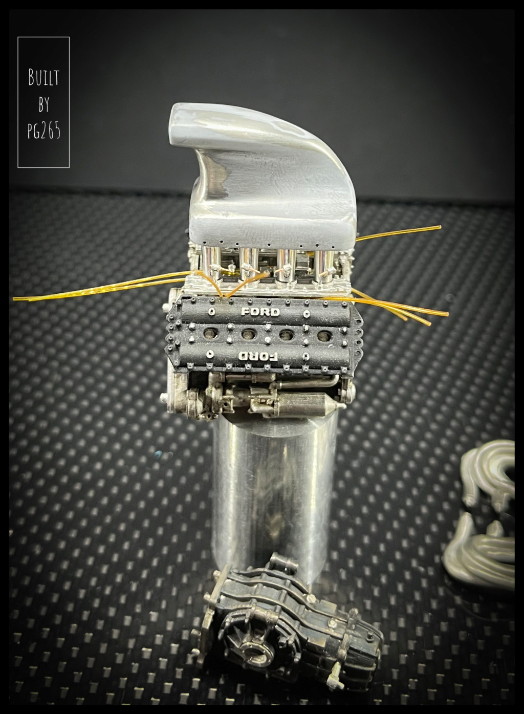
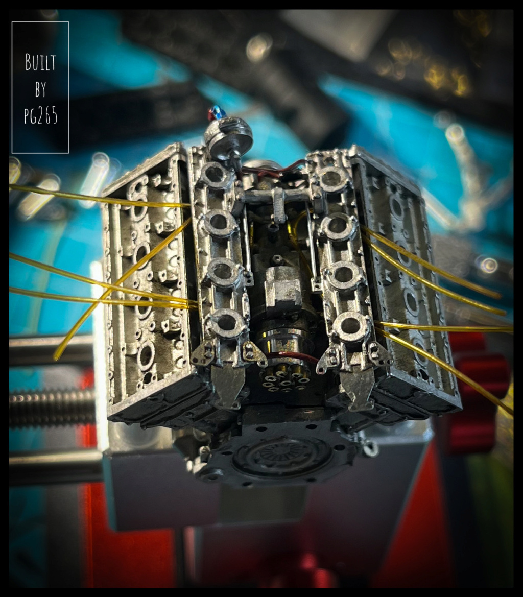
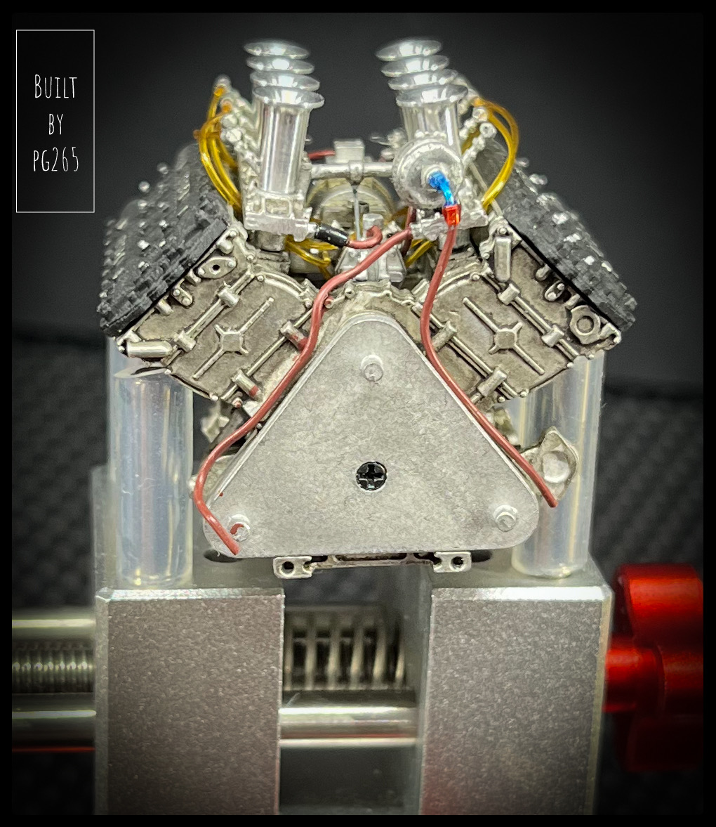
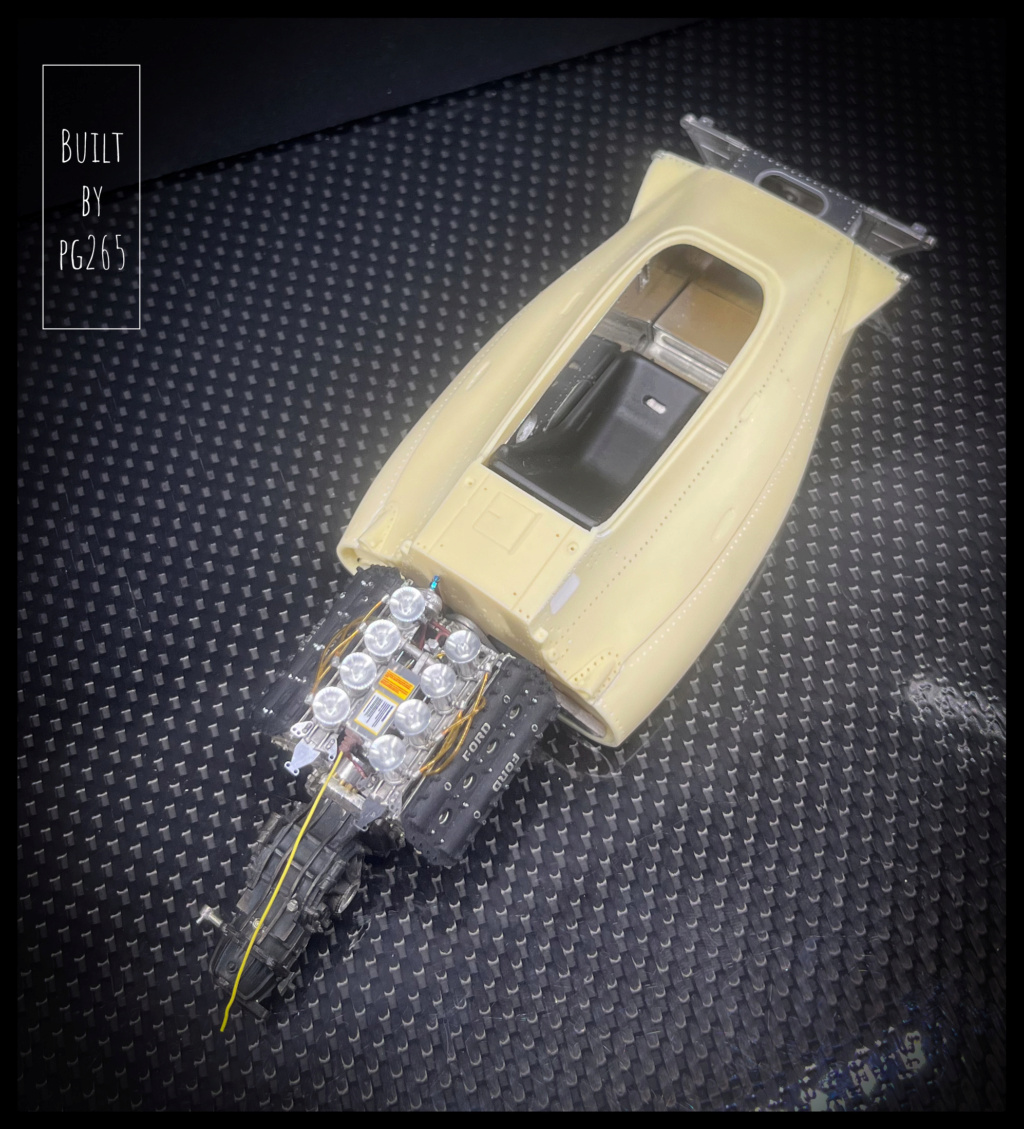
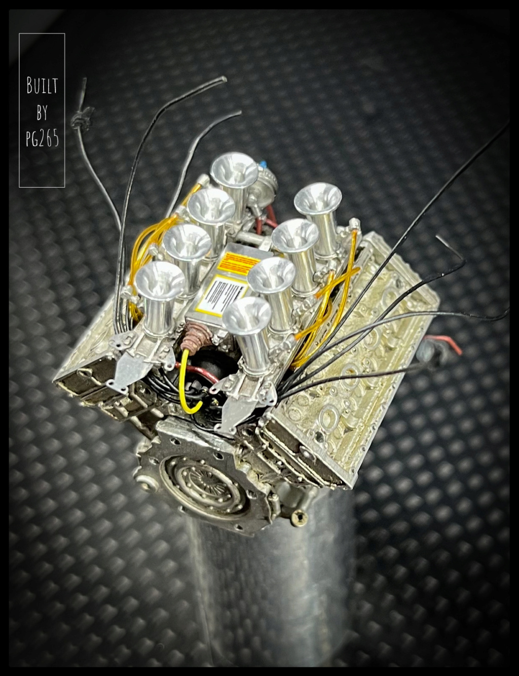
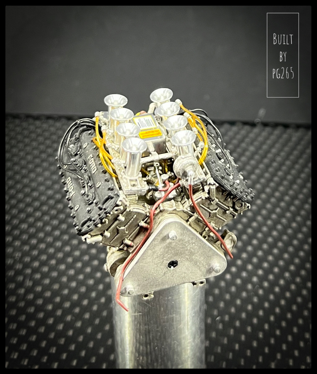
The DFV has made good progress.
Everything is connected, the links are in place.
The velocity stacks are also mounted on the guillotines and connected to the injection pump.
The electronic box is almost finished and only placed in the center of the V for photos.

Image

Image

Image

Image

Image

Image

Here is the small tool made to give life to the discs.

Image

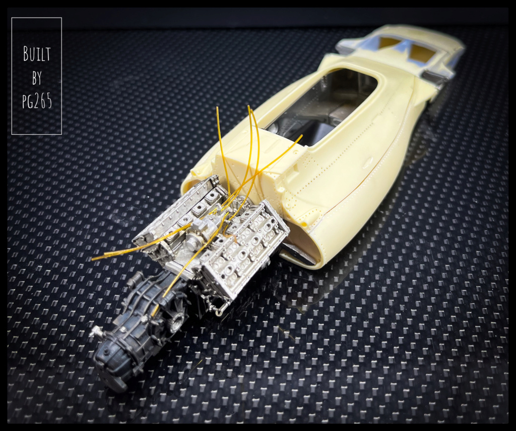
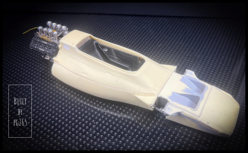
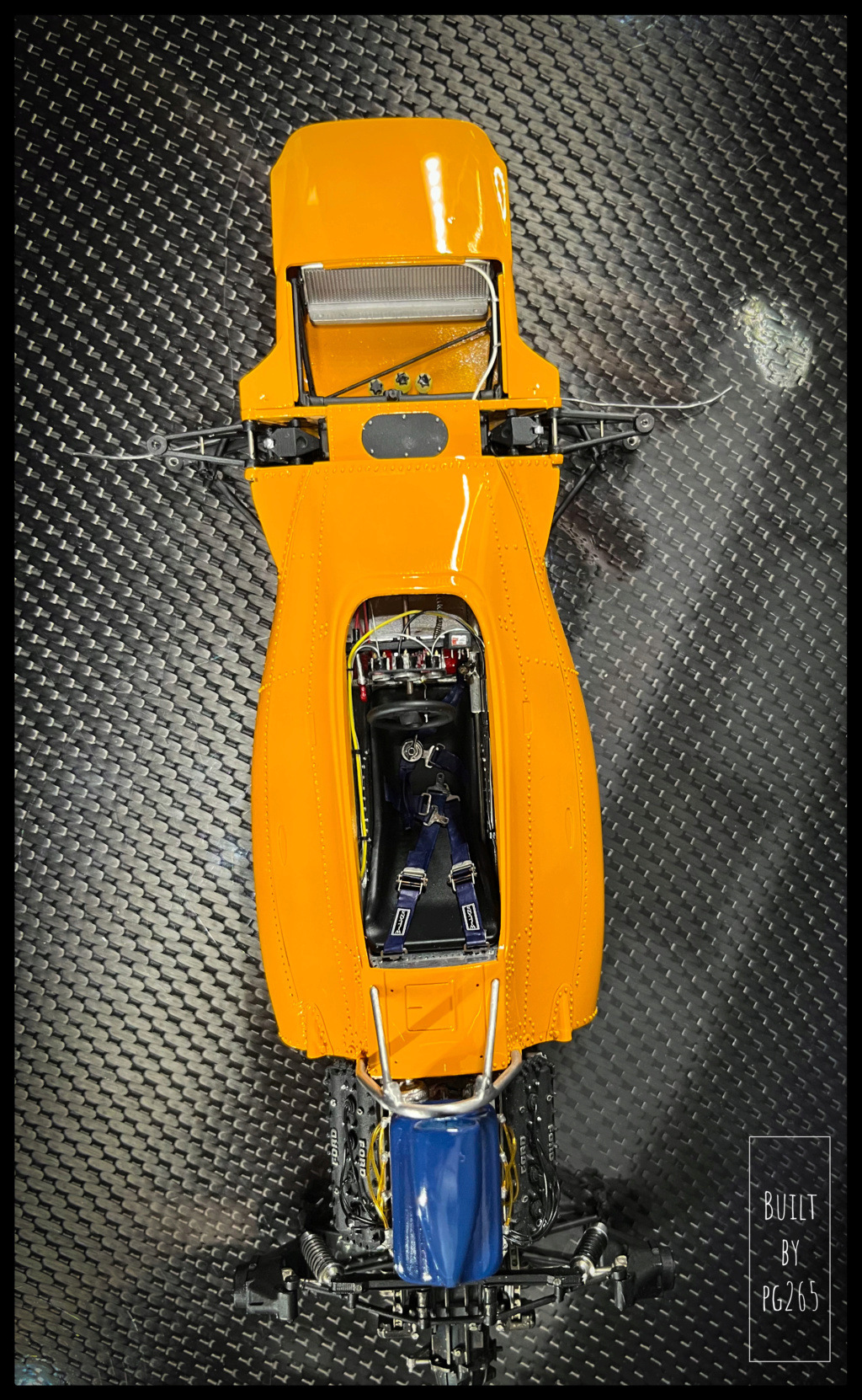
.... and some images of the "motorized" hull.

Image

Image

Image

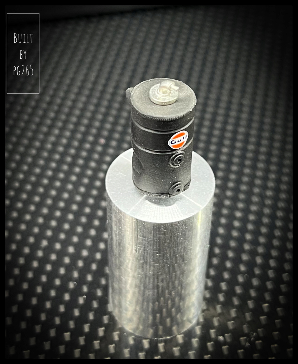
Decided to paint the Delco head to validate the part aspect, I thought that I could also paint the oil overflow can.
It needed a little «facelift» and I confess that I would have done as quickly to make a new one!
In order to straighten the was with a pass along the entire length, I drilled the bottom at 2.1 on 2/3 of the height.
A 2mm brass rod is inserted, glued with CA: this allows to hold the piece in the chuck and to work on its entire height.
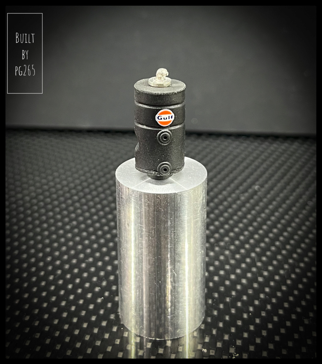
A hole is drilled on the top of the can and a 0.8 brass rod, drilled to 0.55 is installed for more realism.
The retaining rod is then cut and the face is straightened for a better finish.

Image
Sorry for the photo and the «cleanliness» of the room...

Image

The candidates for the primer session.

Image

Dressed in grey.
(GC Dark Surface Primer).

Image

Then in black.
Tamiya X-18.

Image

Image


.... and the piece created, compared to the original one.

Image

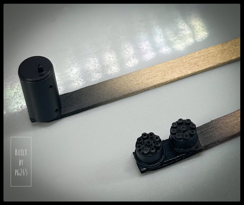
Given its final location, the result is sufficiently convincing.

Session primer for the body.

Image

Image

Image

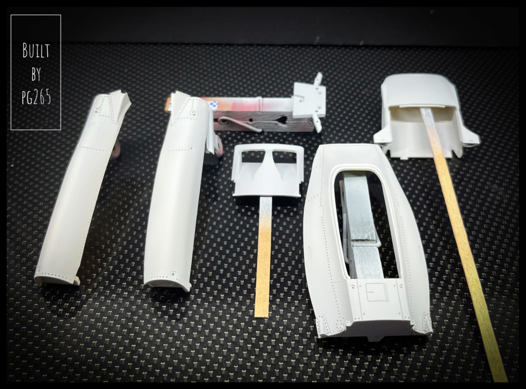
Waiting for his brushing!

Image

Image

As usual, I lay the rivets on the body parts.
In order not to be annoyed with the decals, I delimit the location of numbers that will not receive rivets.


Image

Image

Then the parts are riveted.

Image

Image


They will be taken in places for a better finish.

Others are being prepared.

Image

... And everyone goes back for the painting.

Image

Image

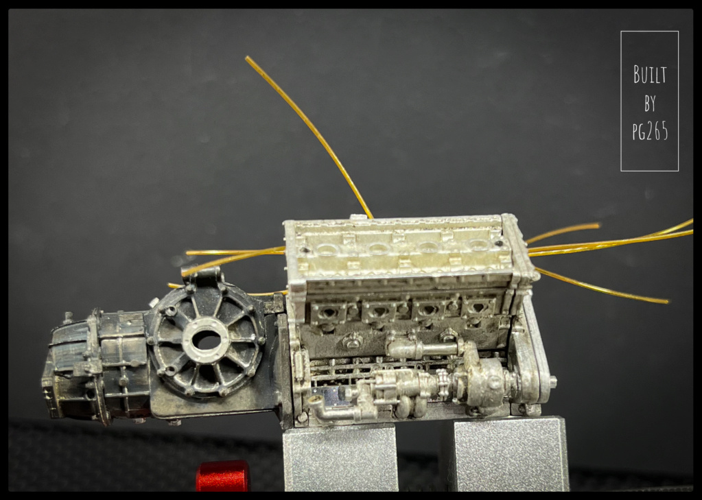
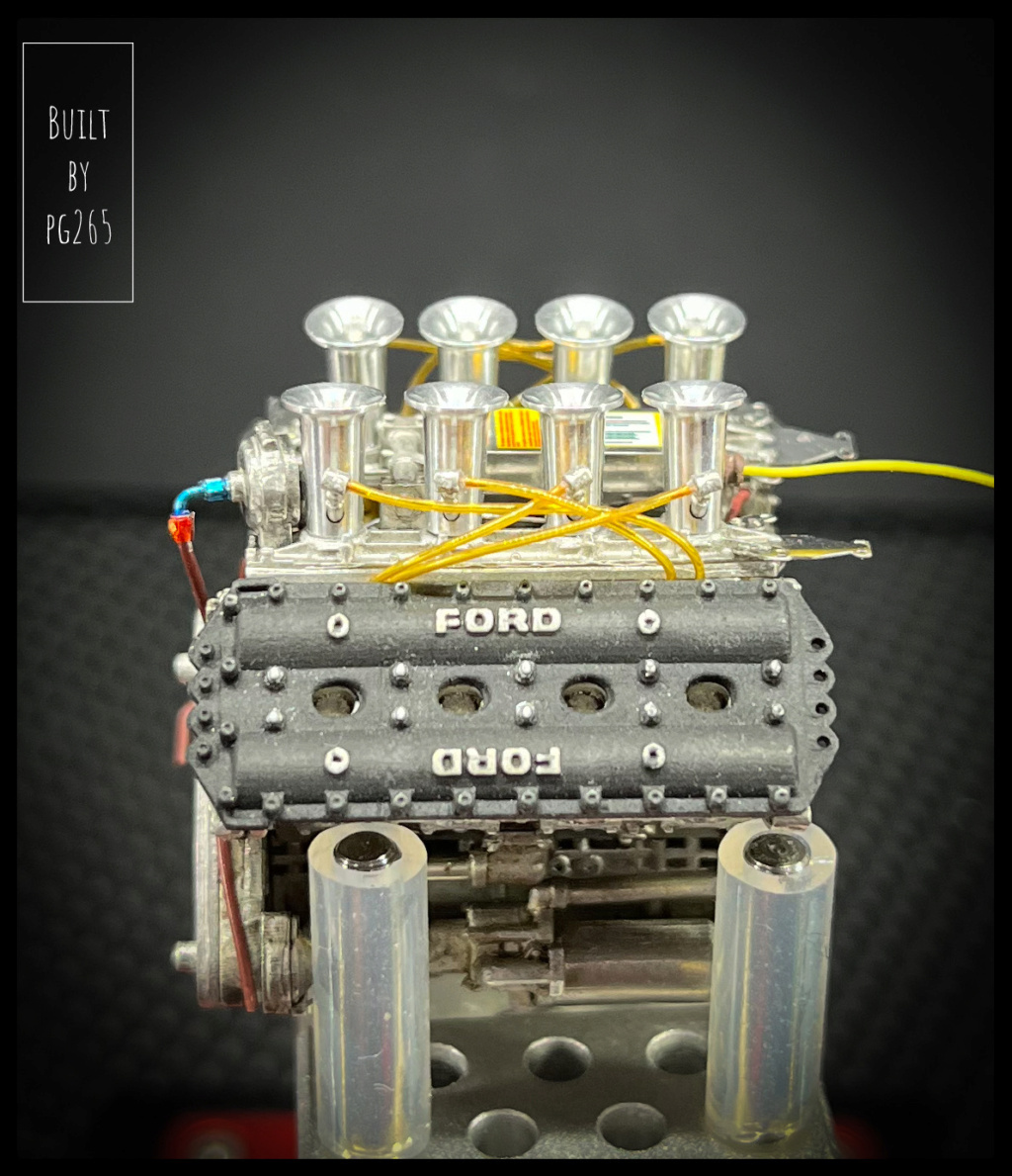
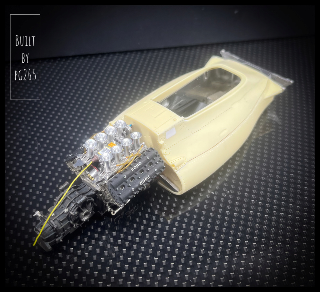
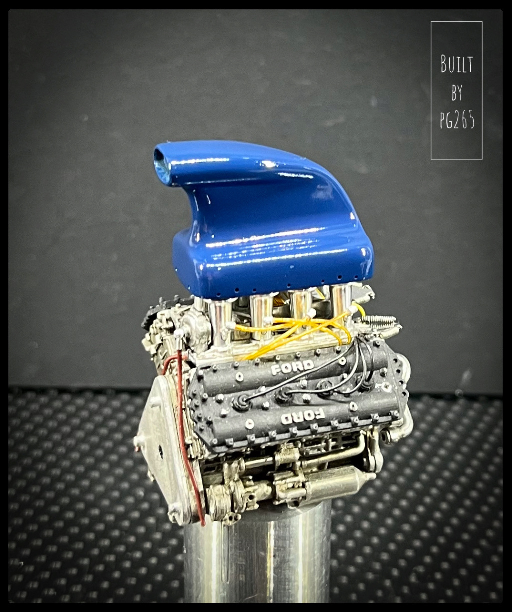
The hair of the DFV «combed», the springs in place, a banjo fitting replaces the A/N... the Cossy takes shape!

Image

Image

Image

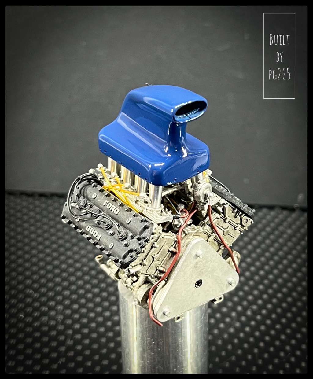
The air duct is painted.

Image

And comes on top of the engine for a little preview.

Image

Image

Image

Some pictures of the body parts after applying the clear coat.

Image

Image

Image

Image

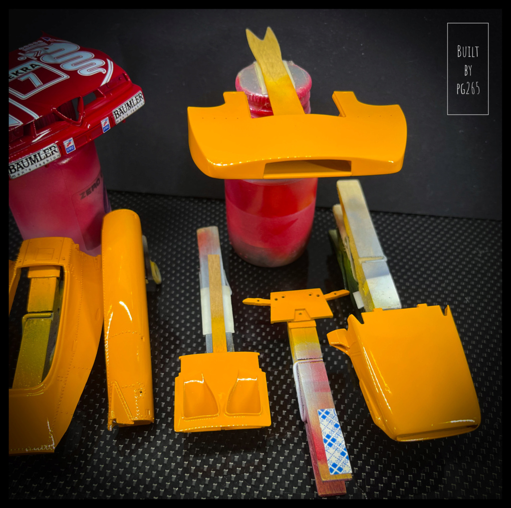
I really like this varnish, which I've been using for years now.
It stretches immediately upon application in a single, thin, wet coat, over a mist coat done  5-minute before. Sprayed at 2 bars, 0.3 Flat Pattern, needle closed 3/4 way.

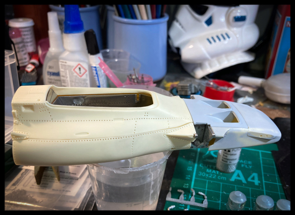
A quick dry assembly of the painted and varnished parts... It's taking shape.

Image

Image

Image

Image

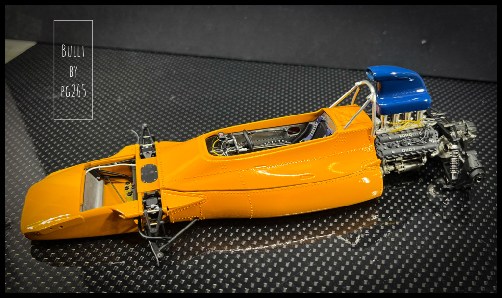
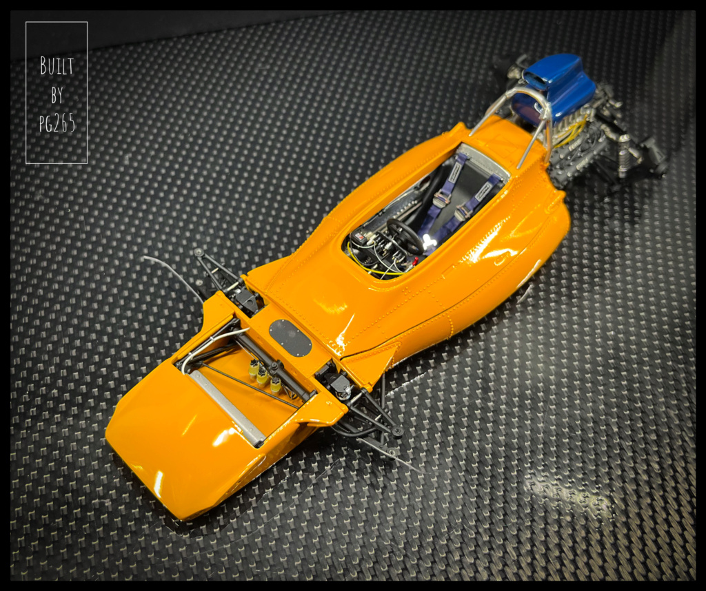
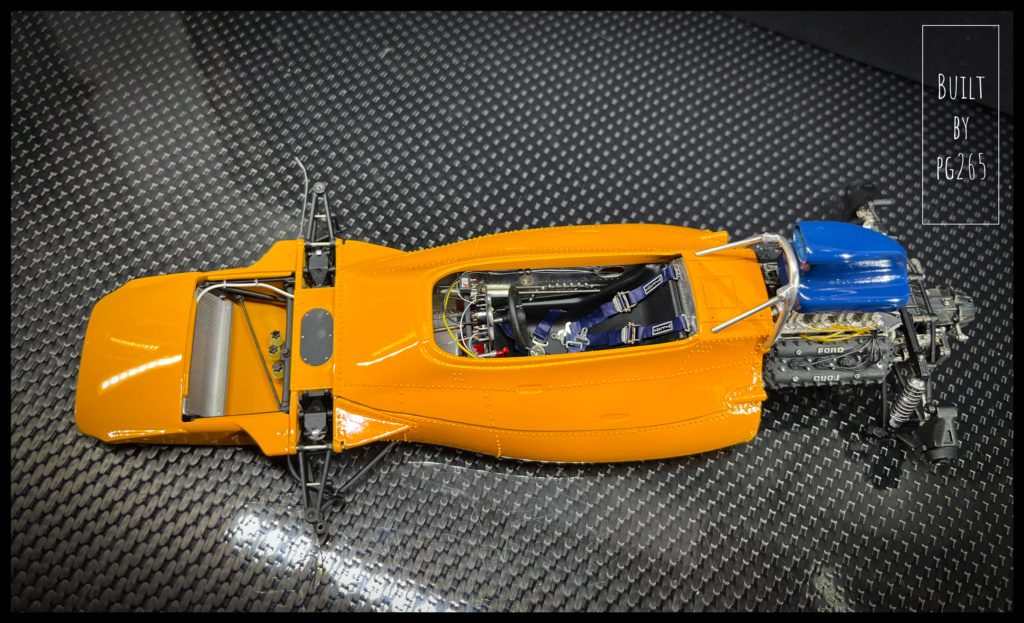
The upper part and the nose are just installed, not glued.
The seam will be much smaller and less visible once the pieces are glued.

Well, the flight activity is slowing down a bit, the weather is less good... I’m taking advantage of a little time to follow up on the beautiful Papaya!
Return to work however on Monday and preparations for my students as part of the aeronautical instructional activity...

I am therefore sorry for this long absence and plan to catch up.

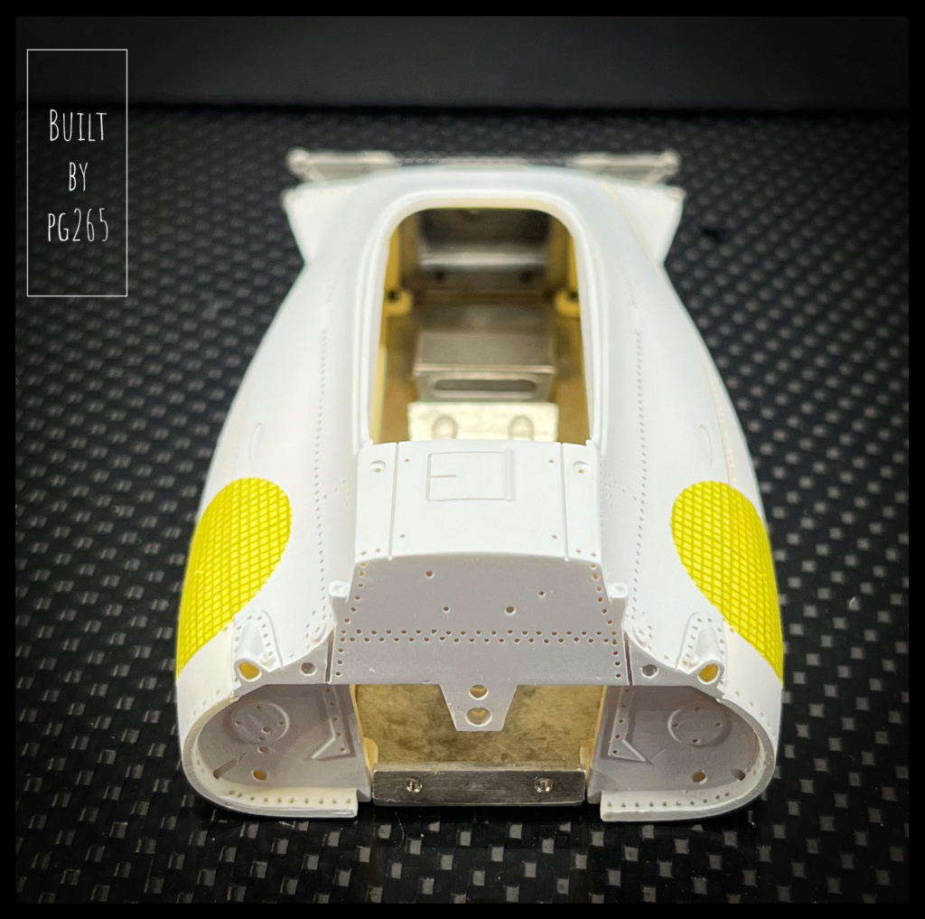
The riveting is done with 0.4 and 0.5 resin rivets.

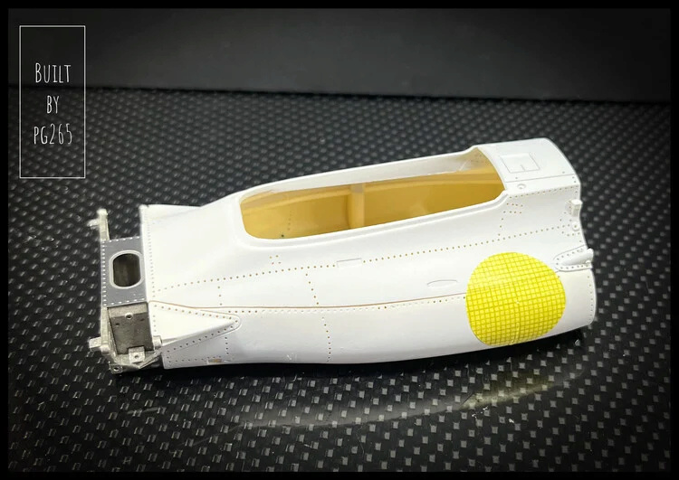
So I prepared the windshield by positioning it on the shell and drilling the holes in its fasteners.

Image

Image

Then the windshield is tinted yellow.

Image

A single dip to obtain the fairly pale shade.

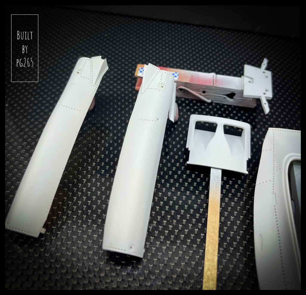
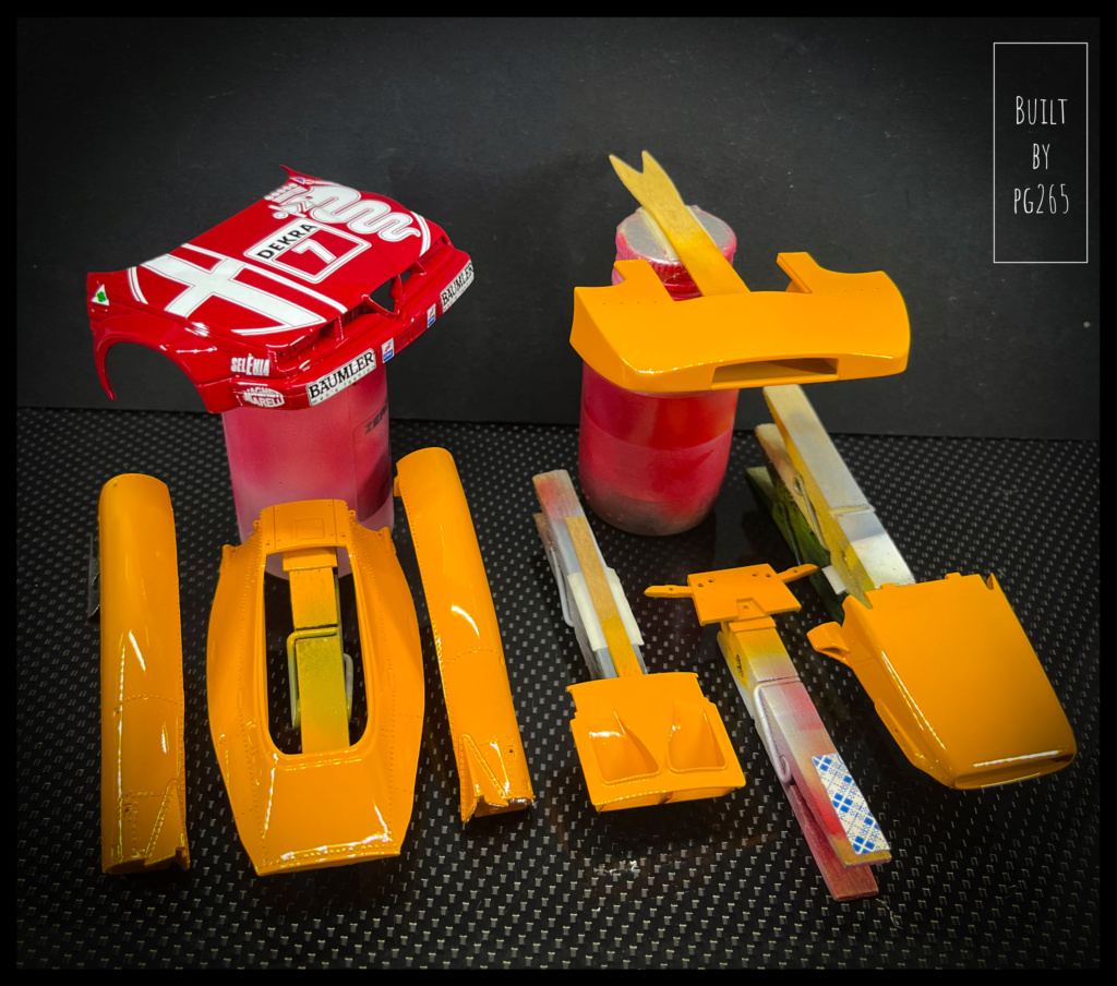
I have also started to be interested in aerodynamic appendages: Rear wing.
The back is composed of a number of parts: White Metal and photo-etched.
The intrados is in three parts; it will be necessary to use some solder for a good finish.
It will also be necessary to polish it with the exception of the small upper plane which is orange and the external part of the lateral fins which is white.
I am not certain of the color of the internal plan of these...

Image

For the front, it’s a bit simpler: orange fins, black leading edge, bare metal end plates.
There are quite a few parts left for the other versions.

Image

As soon as the windshield is fixed, I can devote myself to the decoration and continue with the assembly.

The different parts of the rear fin are welded.
This allows for a nice leading edge.

Image

Image

The whole is then polished.
I deliberately sought a 'mirror' effect on the intrados to bring a little more light to the engine and to the gearbox.

Image

The upper plane, left raw (it must be painted orange), allows to visualize the difference.

Image

The extrados is very slightly sanded with a worn 3000 abrasive sponge.
The central partitions (in two parts) are set up for a trial... transformed!
It is necessary to identify the points to be drilled for their positioning lugs, and slightly accentuate the engraving at the intrados.

Image

Image

I thought it was time to bring a little (more) color there.
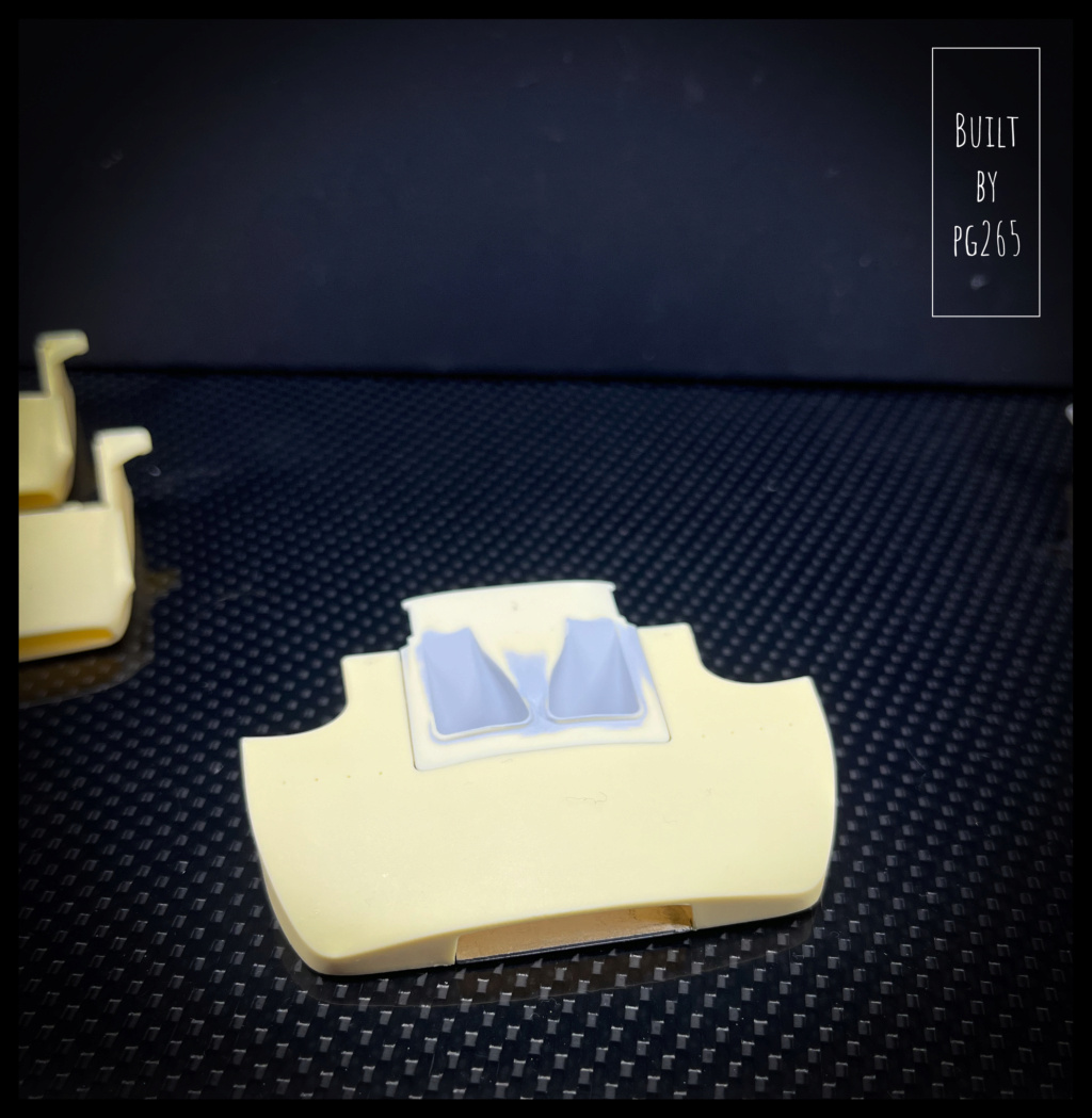
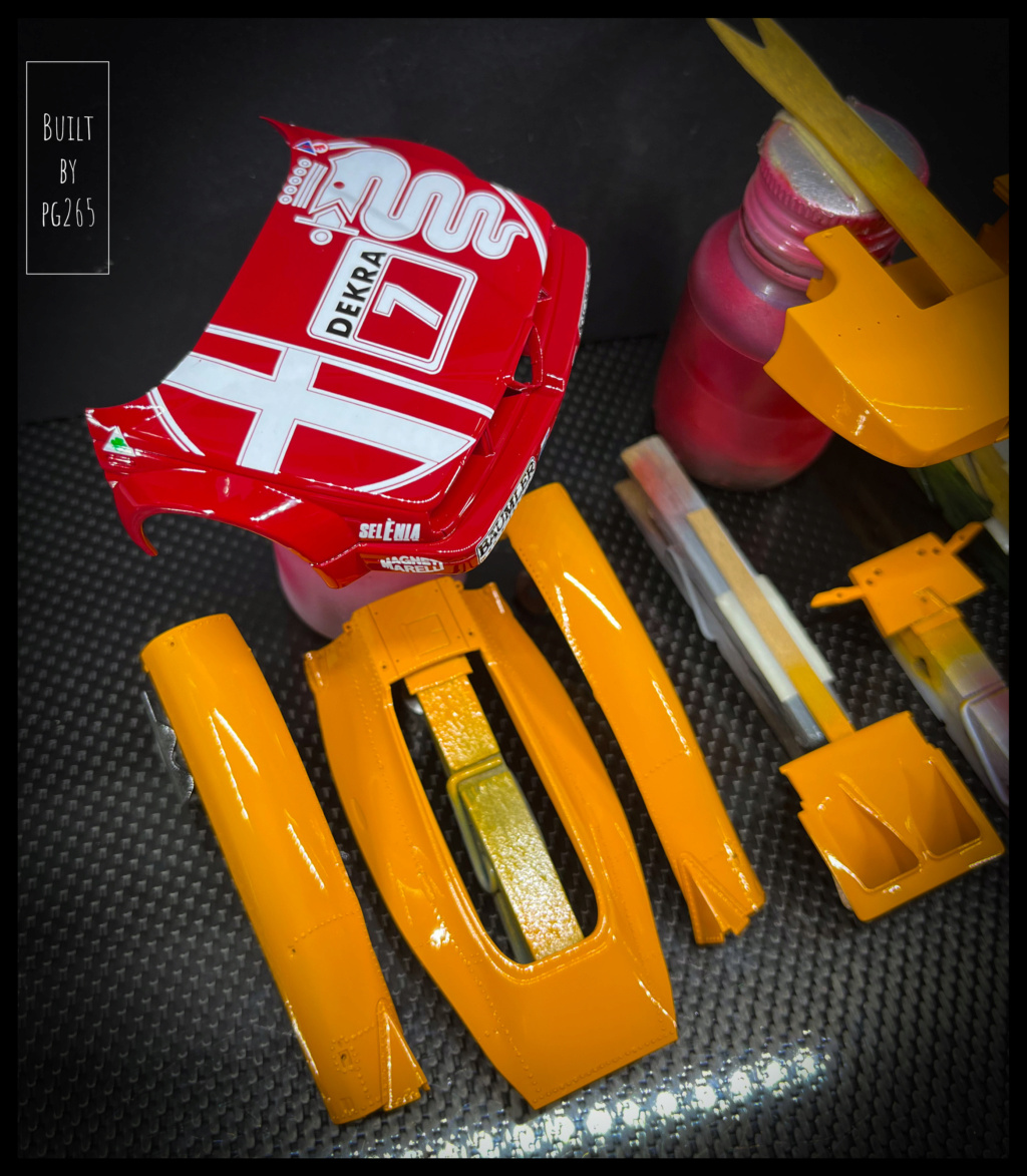
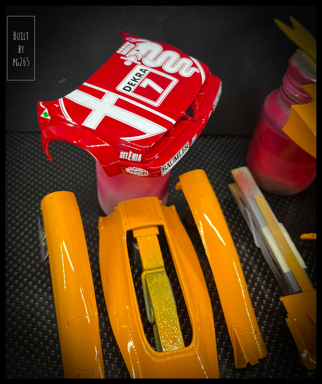
So I started the decoration phase and started with the 'muzzle'.

Image

Image

Image

The decals are splendid although a bit 'stiff', the colors dense and the finish, satin/shiny, of the most beautiful effect.
The contrast with the body parts is discreet but present and representative of the different materials.

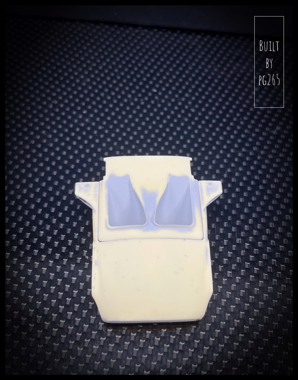
The admission scoop is also partly dressed.
The white is absolutely not darkened by the navy blue, superb!

Image

Image

The windshield is varnished.

Image

Image

Woilà, woilàaa.

More soon.

Pascal.🟠
#WeAreAviation

I’d rather be flying!
User avatar
DRUMS01
Chief Warrant Officer 3
Posts: 2153
Joined: Wed Jun 08, 2016 1:48 am
Location: Ohio, USA
United States of America

Re: Re: McLaren M19A, Denny Hulme, 1972 US GP Watkins Glen.MFH, 1/20.

Post by DRUMS01 »

Top notch as always!

you sir are a modeler's modeler......
On the table or recently completed:


75mm BMW R75 WW2 motorcycle with rider - DONE
70mm Knight on Horse - GB - DONE
1/35 Churchill Mk IV AVRE with Bridge - DONE
pg265
Sergeant First Class
Posts: 302
Joined: Sat Aug 24, 2013 10:09 pm
France

Re: Re: McLaren M19A, Denny Hulme, 1972 US GP Watkins Glen.MFH, 1/20.

Post by pg265 »

Good evening,

Thank you very much.

The windshield is glued on a black seal.
The joint was, variably, present or not...
The rivets will be installed soon.
I have also started taking care of the coolant lines running along the chassis.
They have been filed, sanded, polished, detailed around the fittings...
The left side is done: it was not that easy to set up.
It remains to provide a little detail on the radiator side.

Here are some images with and without the muzzle and/or the extractor.

Image

Image

Image

Image

Image

Image

Image


The upper part of the body is only temporarily placed: there are quite a few things left to do.

Pascal🟠
#WeAreAviation

I’d rather be flying!
User avatar
cor
Sergeant Major of the Army
Posts: 1153
Joined: Sun May 23, 2021 10:34 am
Location: Sydney, Australia
Australia

Re: Re: McLaren M19A, Denny Hulme, 1972 US GP Watkins Glen.MFH, 1/20.

Post by cor »

Thats some nice work in small scale.
pg265
Sergeant First Class
Posts: 302
Joined: Sat Aug 24, 2013 10:09 pm
France

Re: McLaren M19A, Denny Hulme, 1972 US GP Watkins Glen.MFH, 1/20.

Post by pg265 »

Good evening,

Thank you😉

Some progress on the ROOOAAARING PAPAYA.

The wide muzzle of the trials is in progress: Flaps, Duck tape, Dzus...
It remains to paint the extractor and put the race number.

Image

Image

Image

The flaps are riveted: stainless steel rivets flat head 0.4.

Mirrors require a bit of work especially since, too enthusiastic (🙄), I broke through one from start to finish... Repaired by welding, it is then improved with a soft file, sanded then polished.
One finished compared to the other raw.

Image

I also decided to install there, for more realism and especially to please myself, «real» mirrors.

Image

The windshield is now riveted and small washers feature the fastenings inside the cockpit.

The left rear-view mirror is mounted on its folded photo-etched support.
The support is drilled and, also, equipped with stainless steel rivets.
These same rivets are installed on the upper part of the back of the shell.
The right side is waiting for its turn and the locations are properly cleared of paint.

Some decals are placed: The KIWI is here!!

Image

Image

Image

Image

Image

The cooling pipes are treated in the same way as those on the right and then installed.

Image

The connecting tubes to the engine have also been prepared.

Image

A test confirms the proper alignment of the engine, air box and hoop.

Image

More soon.

Pascal🟠
#WeAreAviation

I’d rather be flying!
User avatar
digger303
General
General
Posts: 15755
Joined: Mon Mar 16, 2015 10:01 am
Location: Western Australia
Australia

Re: Re: McLaren M19A, Denny Hulme, 1972 US GP Watkins Glen.MFH, 1/20.

Post by digger303 »

Very realistic .
:clap: :clap: :clap:
:cheers2:
Listen and appear wise
Image
Image

scalemates stash https://www.scalemates.com/profiles/mat ... ION[]=Kits
Image
pg265
Sergeant First Class
Posts: 302
Joined: Sat Aug 24, 2013 10:09 pm
France

Re: Re: McLaren M19A, Denny Hulme, 1972 US GP Watkins Glen.MFH, 1/20.

Post by pg265 »

Hello,

Thank you very much!

Progressing slowly, but surely.
The right mirror is finished then installed and riveted to the top body.
He asked me to do some work with a soft file, then it was polished with paste.

The upper part of the shell has finally been glued to the chassis. The work done upstream allows a rather precise adjustment, in order to obtain a very fine junction: the upper part of the shell was riveted on the lower part.

The hull decoration is then applied: more delicate than it seems, but I expected it for the white circles: not so easy to make the decal conform to the beautiful curves (on all axis) of the pontoons.
Solvent and heater helped me a lot!

Here are some pictures:

Image

Image

Image

Image

Image

Image

Image

Image

More soon.

Pascal🟠
#WeAreAviation

I’d rather be flying!
User avatar
digger303
General
General
Posts: 15755
Joined: Mon Mar 16, 2015 10:01 am
Location: Western Australia
Australia

Re: Re: McLaren M19A, Denny Hulme, 1972 US GP Watkins Glen.MFH, 1/20.

Post by digger303 »

Pretty nice.
:clap: :clap: :clap:
:cheers2:
Listen and appear wise
Image
Image

scalemates stash https://www.scalemates.com/profiles/mat ... ION[]=Kits
Image
User avatar
Gary30
Sergeant Major of the Army
Posts: 1100
Joined: Tue Jan 30, 2018 3:10 pm
Wales

Re: Re: McLaren M19A, Denny Hulme, 1972 US GP Watkins Glen.MFH, 1/20.

Post by Gary30 »

Tres bonne! :clap: :clap:
Portfolio
Click here
User avatar
Kevthemodeller
Lieutenant Colonel
Lieutenant Colonel
Posts: 5596
Joined: Sat Mar 26, 2016 8:31 am
Location: Newton Abbot UK
England

Re: Re: McLaren M19A, Denny Hulme, 1972 US GP Watkins Glen.MFH, 1/20.

Post by Kevthemodeller »

Oh yes :banana: :pop:
Kev

On the bench:
Border Model FOCKE-WULF W190A-8 R2 - 8
pg265
Sergeant First Class
Posts: 302
Joined: Sat Aug 24, 2013 10:09 pm
France

Re: Re: McLaren M19A, Denny Hulme, 1972 US GP Watkins Glen.MFH, 1/20.

Post by pg265 »

Good evening,

Thanks so much for your comments!

The front drivetrain is mounted, steering installed and brakes connected.
Adjustment and small adaptations to make the screw heads flush.
A little acid (burnisher) to darken the brass of the tie rods.

Image

Image

Image

I started to work on the back of the shell in order to quickly install and connect the DFV.
The gearbox should quickly follow!
The wheels are also in progress.

Pascal🟠
#WeAreAviation

I’d rather be flying!
User avatar
Kevthemodeller
Lieutenant Colonel
Lieutenant Colonel
Posts: 5596
Joined: Sat Mar 26, 2016 8:31 am
Location: Newton Abbot UK
England

Re: Re: McLaren M19A, Denny Hulme, 1972 US GP Watkins Glen.MFH, 1/20.

Post by Kevthemodeller »

:th: :pop:
Kev

On the bench:
Border Model FOCKE-WULF W190A-8 R2 - 8
pg265
Sergeant First Class
Posts: 302
Joined: Sat Aug 24, 2013 10:09 pm
France

Re: Re: McLaren M19A, Denny Hulme, 1972 US GP Watkins Glen.MFH, 1/20.

Post by pg265 »

Good evening,

Thank you Kev.😉

A little work on the electric fuel pump, on the connections.

Image

Image

...and quite a bit of other small preparation work on subsets...

The fittings and fuel lines are in place, the mechanical pump is installed on the engine.

Image

Image

Image

Image

Still completing the back of the shell

Image

Then finally comes the time to fix the engine block on it!

Image

Image

Image

Image

Image

Image

Image

Image

With some « clothes ».

Image

Image

More very soon.

Pascal🟠
#WeAreAviation

I’d rather be flying!
User avatar
Stokesy44
Major General
Major General
Posts: 8219
Joined: Thu Jun 18, 2015 10:13 am
Location: The Midlands, UK
Great Britain

Re: McLaren M19A, Denny Hulme, 1972 US GP Watkins Glen.MFH, 1/20.

Post by Stokesy44 »

Amazing work. Incredible detail and skill :clap: :clap: :clap:
Its been tried and tested, it works! So don't blame the system if you're no good. :doh:
Post Reply

Return to “Road Vehicles”