My build started off auspiciously: As I reached over to grab my sprue cutters and free my first part from the sprue, I impaled my thumb on my wire cutters and then spent the next 15 minutes bleeding all over my sprue and workspace….fun! With the blood mostly cleaned up (leaving a little as a sacrifice to the modeling gods), I started to cut plastic.
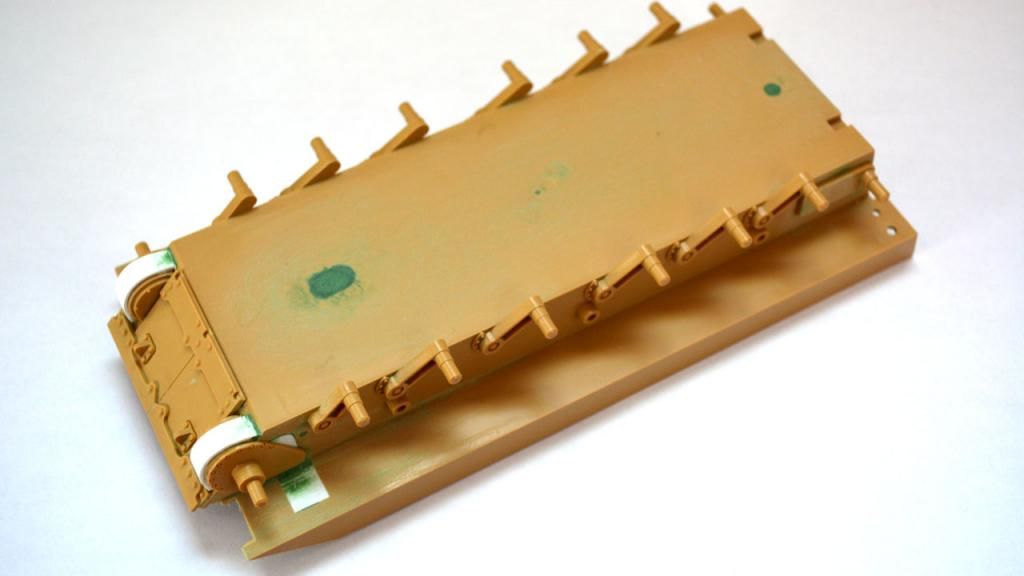
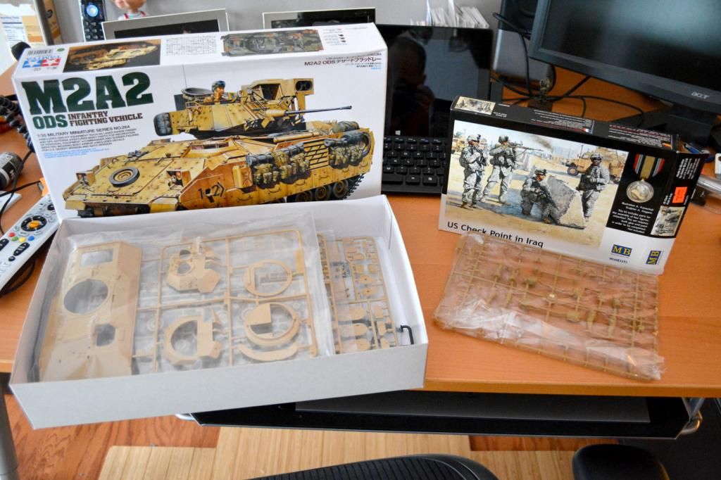
Like the other builds in this SIG, this one starts with wheels and drive sprockets and leads to the lower hull assembly including the loading ramp. This covers the first five steps in Tamiya’s instructions.
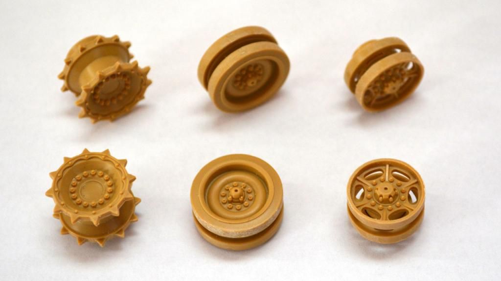
It is fair to say that the suspension with this kit has issues. This is largely because the kit was motorized as many of the Tamiya kits are. The road wheels lack detail, the shock absorbers are not modeled, and the drive sprocket attachment points are wrong. Blast Models came out with a suspension replacement for which looks great, but I’m not shelling out $44.00 for something that is going to largely be covered up in the final build.
The biggest issues, in my opinion, are the drive sprockets and drive covers. The drive sprockets are too shallow and do not include lightening holes. The good news is that the sprockets are mostly covered by the armored skirt and the problem is obvious at first glance.
The drive covers are too small. Pawel Krupowicz (a.k.a., Vodnik) has some nice photos comparing the kit’s covers to the real-life drive covers in part one
in his article about accurizing the M2A2.
I ran through my spares box looking alternate sprockets but I don’t have any good choices. I’ve got Abrams sprockets which look great but are way too big for the Bradley. I even thought about drilling out the lightening holes but decided that it was impractical due to the Because I plan to leave the armor skirt down, I opted to drill out lightening holes and live with the kit parts.
The wheels and sprocket have the familiar seam running along the surface. The seam is fairly significant on the road wheels. I dealt with it using a sharp knife and 100-grit sandpaper followed by some time with my Flex-i-File. Frankly, I like using the rough sandpaper on the road wheels to give them some texture and wear.
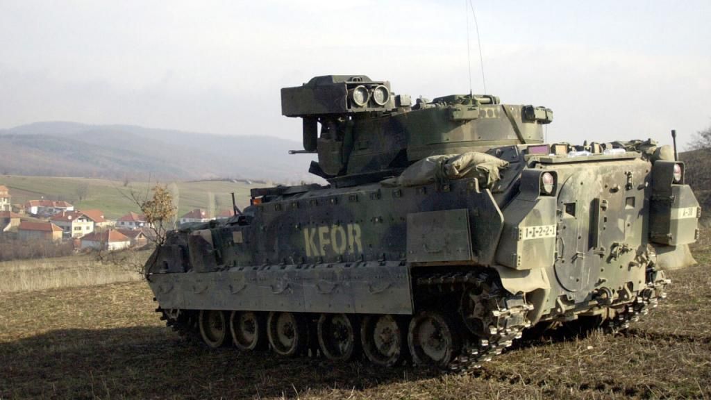
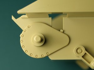
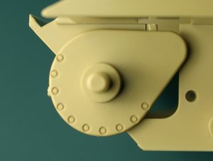
As I researched the drive covers, I found several photos that show that the original drive cover is still there but there has been an extension or protrusion. This could be an additional layer of armor. Or, it could have been enlarged when the engine was upgraded between the A1 and A2 variants. The photo below, shows the shape of the original part and the enlarged area.
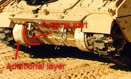
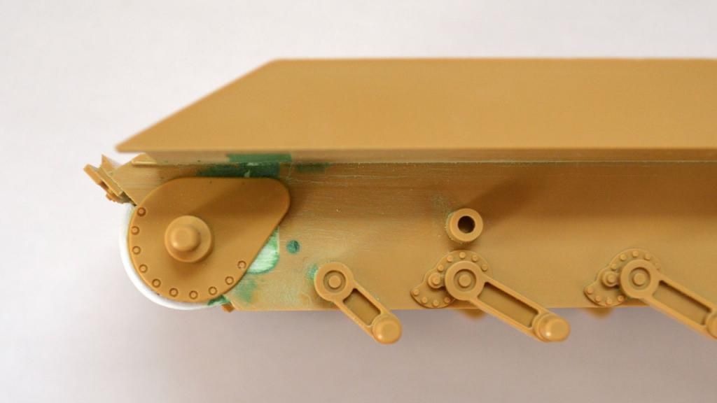
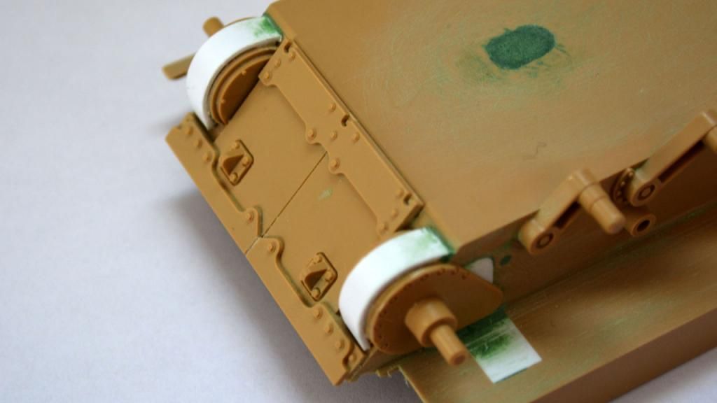
Regardless of what caused it to grow, I realized that I didn’t need to scratch built new drive covers but layer a strip of styrene over the existing covers.I played around with different styrene thicknesses to achieve a passable result. In the end, I went with a 5mm strip of .040 inch styrene. I think that .035 may have been fit the scale better but I didn’t have any of that available.
Because the styrene is thick, it didn’t want to follow the curve of the drive cover. I thought about applying heat to it but have
run into problems in the past with this technique. So, I opted to apply plastic cement a small portion of the drive cover. Once dried, I cemented another small small portion and let that dry, repeating the process until the styrene wrapped the drive cover. I then trimmed the excess styrene from the ends.
Next, I turned my attention to part E26. This part represents armor that has been bolted on the front of the lower hull. In fact, the greatest clue that the drive covers are oversized is by looking at this piece compared to photographs of the real tank. Compare the photo below from Krupowicz’s article with the photo of the actual tank above.
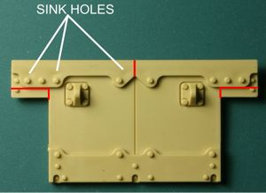
Krupowicz shows how the red areas on the left and right of E26 should be removed to match the reality. Also, the top armor plate needs to be split. The surgery in both areas was quick and easy. Also, as a side note, my part did not include the sink holes that Krupowicz points out. So, no repair was required.
With E26 modified, I mounted it on the lower hull before fitting and finally dementing the drive covers in place. I did all of this before mounting parts B61 and B62, the left and right attachment points for the drive sprockets which was a break from the instructions.
As Krupowicz points out in his article, B61 and B62 are not attached to the lower hull correctly in Tamiya’s kit. The top photo below shows how Tamiya wants to you mount B61 while the bottom photo shows how it should be mounted.
Compounding this problem, the location of B61 and B62 needs to be slightly higher with the drive covers enlarged and surgery performed on E26. Therefore, I removed the attachment pins and most of a ridge along the rounded portion of the part (leaving some to help place the part against the drive cover).
With all of this done, I pulled out styrene and putty and started filling in all the holes in the lower hull that Tamiya included for a motor and parts.