Yes I know about a week later than planned for this, but thats me with modeling it seems. A week late and a dollar short, as they say.
Here is the current layout of my Naboo project so far which took quite a while to do and compile photos.
The top few pieces showing a fuselage both chromed and top sprues and some small parts are from my old model that was replaced by a new ones below. Those were the leftover TET spill pices now used for testing.
I will attack what has been done so far with the wing section in this post and shown at the bottom.

OK, LEDs to me are very simple display devices to deal with being in engineering most of my life. Plastic model kits are still a hard thing for me (not to build) but with painting, at the moment tho, this is not an issue yet but one that I hope to accomplish soon.
When I got my Naboo for my 1st ever build on this forum, I said, no problem, its simple, we have many months to do it and I’ll have a lot of time to put a bunch of LEDs into it. I was more worried about the paint colors at 1st. The cockpit LED display will look cool and the engine having that blue exhaust will look neat, not to mention the LED laser light as well, up front in the bottom area. This is the main laser that took down that starship in the phantom movie. I will have 2 leds there too if you remember.
I will not talk about the Laser lights, R2D2 led or the cockpit leds yet but will in future updates. I concentrated everything on the engine exhaust for this post. As I found out later this would have stopped me cold if I started doing that at 1st long before I spilt TET all over the wing areas. That was a major mojo killer for me for a while as well. I bought this kit twice.
I drew a diagram or even better made a picture of the side of the engine exhaust areas where this is the hardest issues I had to tackle here. Keep in mind; I was into engineering long before I came back into modeling. Hmm, in modeling this may hurt me more I think, the more I get into this. I still can’t paint a barn door, but pushing electrons used to be easy for me.
OK, more of this LED display construction. I think you can see what I saw with the integral structure of the connection points that held the rear thin wing shafts below. No light escape areas. At all.

There is no easy way to get leds to push the light onto the areas shown in the movie, short of the digital effects that I am sure was used back in the 90’s. How to get an LED on the left to illuminate the rim area on the right that surrounds that drum with that pointy thing.
Here is an actual view of the engine exhaust area. (ok turned the other way)

OK what do we do now to show LED stuff? I tried many experiments to somehow sneak a blue led (or many leds) to get this thing to glow and look a bit real (movie wise)
The 1st experiment was to put an LED in the exhaust area with very tiny holes mounted all around it (here, just a few in 1 area to test this) Naaww, not good at all. Too much pin-cushion like effects. Even tho it does not look very blue? … it is in real life, but silly looking and ILM would laugh at it too.

Next was a complete rounding of the exhaust point like area thingy exiting from the engine drum similar to the above but using a greatly modified redesign to somehow get the blue led to shine onto that point. Note the green standoff sprue below to hold a very weak exhaust port.

Here is the led test below using this second approach. It seems a bit bright at one angle but almost gone on another. Note: that the LED is very bright here but only in these pictures. Its not that bright in real life, and its more blue-ish as well.

Its OK kindof??… but it is very hard to see at many angles. If you were to look from the front you could not see anything. Nope, this is not good enough as well and if you saw it on my bench with this camera at that angle you would say… Hmmm, its ok but seems very weak.
The last and most successful approach and one that I went with towards the middle of last month is the following redesign of the engine exhaust areas. Inside that curve of the top half of the engine area you can see on the right a few holes I drilled into it to start with. Then to the left with a large final hole and some removal of that areas on the pointy posts below (which is a bit blurry and missing the points). I made them as wide as I could without messing up the structure.
Both sides would have that large hole, sanded down rim and even the long pointy drum post that was opened on the edge to allow the Krystal Clear to pipe the light out of the LED. Look at my drawing below this for a better Idea of what I did.

This allowed me to position 1 of the 4 LEDs in a position that got the light pipe effect on the Micro Krystal Klear that wrapped around it as a replacement of the rim.
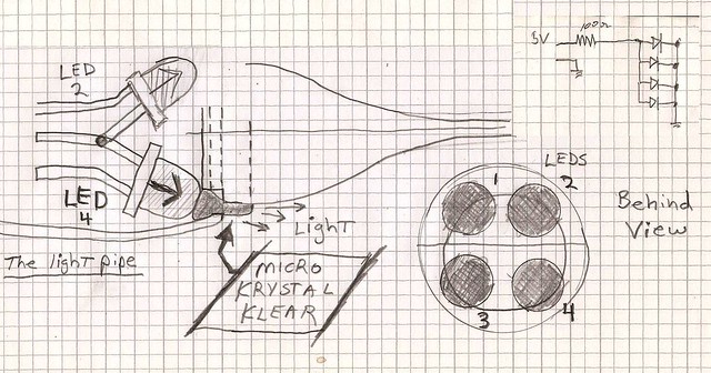
As just mentioned, I am replacing the RIM with Micro Krystal Clear to form a light pipe.
The top pic, normal rim from the kit. Second pic, the new modified rim area with the light pipe.

Please notice I spent many weeks just applying Micro Krystal Clear over and over (after careful sculpting) into the engine areas at an angel that would allow maximum light out of it. I put down an application in 4 areas on both sides, (8 total, one for each LED) trimmed to shape and then another coat of KK. I think I did three or four coats.
Copying the rim at the engine area of the engine exhaust port was the best way to travel the light around that point and still keep the structure of the model. It was almost the same as the model but now it had a clear ring around it. See below where that rim is and how it glows when the engine is on with just one port side.

Side view of just the top port side with power.

There is a Krystal Klear port under each LED on both the left and right halves of the wings. 8 total as you can see below. NOTE, there is small notches every 90 degrees showing a small gap. These are holding posts for the exhaust pointy like shaft thingies. A complete rim of KK could have held it, but I chose that for strength here. They lock in solid and when I need to paint it soon they could break off too easy. Yes I know the purists will be screaming at me, but dang! If I see any more LEDs in these wing areas, Im gonna loose my mind. I could have built this kit 9 times already. When the LEDs are on though it does look like a nice glow around those areas similar to the movie at any angle.
You can also see the two wires going from the middle of the wing (buried into the wing grooves) and held by putty. There were 3 grooves on each side. I put 2 wires (+ and -) into 2 grooves and the last not used. Its not just artistic license here, its really the only way to get wires out to the LEDs and only remove some detail from the bottom.
The wire is 30 gauge wire wrap wire you can find on fleabay. Hopefully it will be invisible when the fuselage is connected and painted. There will only be one groove visible now but that is at the bottom. The top groove is negative polarity, the bottom is positive for a 5 volt connection. Even though you can see a few resistors here I am using a total of 100 ohms for each wing with 4 LEDs in parallel. You can see the schematic for that in the drawing.

Here it is fully powered up: Notice the glow on the light pipes directly under the LEDS. The outer two has the pointy posts under them but no point tips, but Im sure you get the idea with that. These were test ones.

A back view.

Back view, closed up with no pointy post assemblies at all. I think you can see the nice uniform glow.

Well that’s it for the moment. The pointy posts lips on both need to be carved to fit both sides when closed (as well as the points attached) They are so small and breakable I did not complete them yet, what you see are my test ones from the old model.
You can also see below the four 90 degree sections cut out for the leds to pipe out the light into the Krystal Clear rim shrouded around the engine exhaust. See the drawing #2 up above again to understand how I got that led light to creep out just along the edge if you still dont see what I did here. It even behooved me a few times when making it.

Finally: You may have not seen a blocking black paint interior here for a very good reason. It will be on the outside when I put the gloss black down, covered by Alcal II Chrome or whatever I use. Here is why.

The yellow absolutely destroys the blue LED light as you can see on the middle picture. I have 3 images here. The 1st one shows the raw blue LED light alone. The last drawing on the right has the LED which is behind it and just one coat of black paint over the top. No light leak at all. I think if this were white plastic, it would glow like crazy. Im not sure, this is my humble opinion based on what Im seeing here. Any thots about this please reply.
This along with the fuselage bottom with the laser LEDS and cockpits LEDS will be my next update but I got to get back to my Space SIG rocket so it may be a short while. I may tho put in the lighting of R2D2 which I am almost done with as well, so maybe soon with him.
Thank you for stopping by and looking!